Table of Contents
ArmA 1 Material Editor Tutorial
ArmA 1 Forum, ArmA 1 Home, ArmA 1 Config, ArmA 1 Tools, ArmA 1 File Formats, ArmA 1 Missions, ArmA 1 3D Modeling, ArmA 1 Terrain, ArmA 1 Texturing, ArmA 1 Scripting
ArmA 1 aka Armed Assault (ArmA)
Material Editor Tutorial by Linker Split
Purpose of this tutorial
I decided to write this tutorial because it's a very useful program if you want a good model to be correctly rendered ingame.
It seems to be hard to use, but I can assure it is not as you can think. The purpose of this program is simply to create particular effects on textures that you apply to the model, such as Specularity, Reflection, material in general.
Indeed MatEditor generates a RVMAT file that you have to apply to the model itself via modeling program Oxygen 2, then you will see the results on buldozer.
Configuration
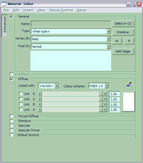
After having installed the program, you will have this window:
Before using MatEditor, you should configure it, in order to have a clear point of view about it, and its power.
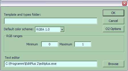
First, go to File → Options… A window will pop up:
In the “Template and Types folder” you must put the MatTemplates located in the subcreted Drive P:\ (when you install O2, you will have the P:\ drive) so, your line would be:
P:\MatTemplates
Then you have to select your preferred text editor (I have editplus2, EditPadPro is good too)
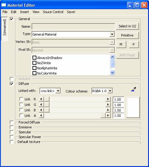
Now after this passage, if you go to the main MatEditor window, you’ll see this:
Now the second and secondary step is to configure your own RVMAT options (in case the default templates don't fit your needs)
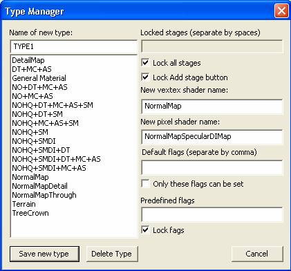
Click File → Type manager and another window will pop up:
Here it is were you define flags, vertex shader, pixel shader and so on.
Before going on, you should know what you are going to do:
Render Flags
Render flags are Special shading properties that are used instead of old Vertex Lighting Property settings. The options are:
- NoZWrite
Face is not counted in Z-buffer. Used for alpha transparent surfaces laid over another face to fix shadow artifacts. (for example squad logo).
- NoColorWrite
Disables calculation in color channels. Face is calculated just in alpha and Z-buffer.
- NoAlphaWrite
Disables calculation in alpha channels. Used for transparent glass that has 2 pass material.
- AddBlend
Allows adding alpha transparent surface color to the background. Used for fire particles.
- LandShadow
For terrain.
- AlphaTest32
Defines threshold where pixel becomes transparent at drop off to discrete alpha. The bigger value, the more pixels are used (Alphatest64, Alphatest128)
So, let's proceed:
Create a new Type, and name it like I did (you can of course choose another name).
Now thick the boxes as in the image, and add properties to the Vertex shader and pixel shader.
I recommend you to use for the first Type the following properties:
| New vertex Shader name | New Pixel Shader name |
|---|---|
| NormalMap | NormalMapSpecularDIMap |
A little explanation before going on:
Vertex Shader Properties
Are used to define how ArmA engine must work with the models.
The options are:
Basic
no extra info
NormalMap
normal map
NormalMapDiffuse
normal map + detail map
BasicAlpha
basic with per-vertex alpha
NormalMapAlpha
normal map with per-vertex alpha
NormalMapDiffuseAlpha
normal map + detail map + per-vertex alpha
ShadowVolume
shadow volumes
Water
per-vertex water animation
WaterSimple
per-vertex water animation (without foam)
Sprite
particle effects
Point
anti-aliased points
NormalMapThrough
normal map - tree shader
NormalMapSpecularThrough
normal map - tree shader
TerrainAlpha
terrain with alpha mask - based on VSNormalMapDiffuseAlpha
Terrain
one pass terrain, no alpha mask - based on VSNormalMapDiffuse
BasicAS
ambient shadow
NormalMapThroughNoFade
normal map - tree shader - without face fading
NormalMapSpecularThroughNoFade
normal map with specular - tree shader - without face fading
Pixel Shader Properties
Are used to define how ArmA engine must work with the models.
Normal
diffuse color modulate, alpha replicate
NormalDXTA
diffuse color modulate, alpha replicate, DXT alpha correction
NormalMap
normal map shader
NormalMapThrough
normal map shader - through lighting
NormalMapSpecularThrough
normal map shader - through lighting
NormalMapGrass
normal map shader - through lighting
NormalMapDiffuse
NormalMapDiffuseMacroAS
NormalMapMacroAS
NormalMapSpecularMap
NormalMapDetailSpecularMap
Similar to NormalMapDiffuse
NormalMapMacroASSpecularMap
NormalMapDetailMacroASSpecularMap
NormalMapSpecularDIMap
Same as NormalMapSpecularMap, but uses _SMDI texture
NormalMapDetailSpecularDIMap
NormalMapMacroASSpecularDIMap
NormalMapDetailMacroASSpecularDIMap
Detail
detail texturing
Interpolation
Water
sea water
WaterSimple
small water
White
WhiteAlpha
AlphaShadow
shadow alpha write
AlphaNoShadow
shadow alpha (no shadow) write
Terrain
DetailMacroAS
Grass
Special shader to allow volumetric shadows to be cast on grass clutter
The ones we used are the best for a model.
Now press “Save new type” it will close automatically the window, returning to the main one.
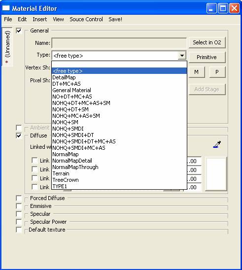
Select the “Type” box, and change it from <free type> to “type 1” (the one we saved) as I did in the image below
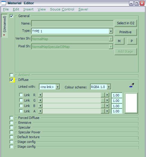
After having selected it you'll have this one:
Can you see at the bottom 2 identical boxes: stage config.
You need them cause a material is defined by the Normal map, and the specular map. That is the way to define it.
Go to Insert → Panel → stage and do it two times so you will have two stages as I did.
Let's start the real tutorial!
Creating The Material
This is the most important part of this tutorial since it explains how to create the “effects” on models.
Before continuing I recommend you to take a look at my Tutorial about Normal and Specular mapping tutorial.
So let's make a metal material for example. We need to define the Ambient, the Diffuse, the Force Diffuse, the Emissive, the Specular, the Specular Power and the two stages.
So thick all boxes from the first to the last except the “default texture” one (because it's useless now), and combine the R G B A channel to have some effects.
I recommended you to study my Normal and Specular mapping tutorial in order to choose the right colors to be used.
Little Trick: link the R,G and B channel together, don't move them randomly, but always linked
So we want a metal material, don't we?
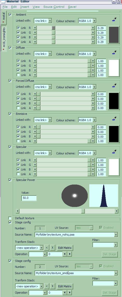
Configure the properties as in the image:
As you can see, in the two “stage boxes” I added the source name of a normal map texture, and of a Specular map one. For your model you should do the same.
See, UV SOURCE has been set to tex.
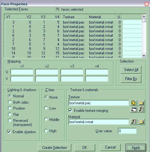
Now simply save the work as metal.rvmat, open O2, select the faces you want to have the new material, press E and in the “material” box, write the path to the file:
Now run your buldozer, and see the results!
I hope this tutorial will help all model makers! Thanks all for your effort! Now it's better if you sit on your chair, and start modding!
Cheers folks Linker Split
Notes
This tutorial was written by Linker Split, thank you for granting permission to host this on our wiki.

