Table of Contents
ArmA 1 Normal and Specular Mapping
ArmA 1 Forum, ArmA 1 Home, ArmA 1 Config, ArmA 1 Tools, ArmA 1 File Formats, ArmA 1 Missions, ArmA 1 3D Modeling, ArmA 1 Terrain, ArmA 1 Texturing, ArmA 1 Scripting
ArmA 1 aka Armed Assault (ArmA)
Normal and Specular mapping by Linker Split
Introduction
I decided to write this tutorial because I came into the deep process of normal and specular mapping with my HDT island.
The process isn't easy, since you should have experience with many graphic tools like Adobe Photoshop, or Maya and 3DStudio Max. ArmA, unfortunately, use a different method of applying NormMap: you'll have to write some C++ code lines into your main config.cpp in order to define it, but I'll clear it up afterwards.
Some definition
Before starting, it would be good to make you understand what we are going to do:
Normal mapping
Is the technique to replace the existing normals on model. It can be used to greatly enhance the appearance of a low poly model without using more polygons, so we could have a 2.000 poly model (very poor model) with a lot of details.
Specular mapping
Basically in real life every highlight in an object is actually a reflection of a light source and specularity is a way to fake those reflections by placing a highlight in the position that the giving object would be reflecting the virtual light.
Bump Mapping
Are textures that store an intensity, the relative height of pixels from the viewpoint of the camera. The pixels seem to be moved by the required distance in the direction of the face normals. You may either use greyscale pictures or the intensity values of a RGB-Texture.
Tutorial
Let's start!
Ok, in this tutorial, we are going to make a simple normal mapped cube with a texture applied to it. I can assure the results will be very good.
Point 1: First of all, make sure you installed all the required tools:
Download and install Kegetys ArmA tool (in particular PAAPlugin) Download and install Adobe Photoshop Normal Map and DDS Authoring Plug-ins (for users with a NVIDIA GPU) or Download and install ATI's normal map generator program (for users with an ATI GPU). However even if you have ATI card, you can as well use the NVIDIA plugin for Photoshop, it works just fine.
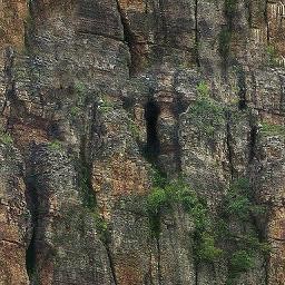
Point 2: Now Open your Adobe Photoshop and create a new image, 256×256 px, and paint something like in this one:
(remember to have it in RGBA format, neither greyscale or other formats).
Point 3: Now save your Image as TGA, so: tex1.tga, 32 bits/pixels. Then open TexView 2 and save the file as tex1_co.paa
Now, why did we save it with _co.paa extension? It's easy, cause in TexView 2, this extension means: color (difuse map)
Point 4: Now that the texture has been done, create a folder, call it BOX, and cut and paste the file in it. (se we have ..\BOX\tex1_co.paa) open up Oxygen, create a new cube, and apply the texture. Save the model as box.p3d:
(if you can't use Oxygen, I invite you to follow Brsseb tutorials).
Point 5: Well, we created a very simple model (indeed for a tutorial we don't need a UBER 30000 poly one) Cut and paste it into the BOX folder (as for texture tex1_co.paa).
And the little part of the addon has been done. Now let's proceed to the difficult one.
Creating Normal Maps
Ok, let's proceed to make a lifting for it!
Point 1: Open up your Photoshop, and open the texture tex1_co.paa thanks to PAAplug by Kegetys. Now, I have a NVIDIA Graphic Card, so I'll explain the process for NVIDIA USERS, even if I think for ATI USERS would be the same.
Go to the Photoshop menu Filter and then NVIDIA tools → Normalmapfilter:
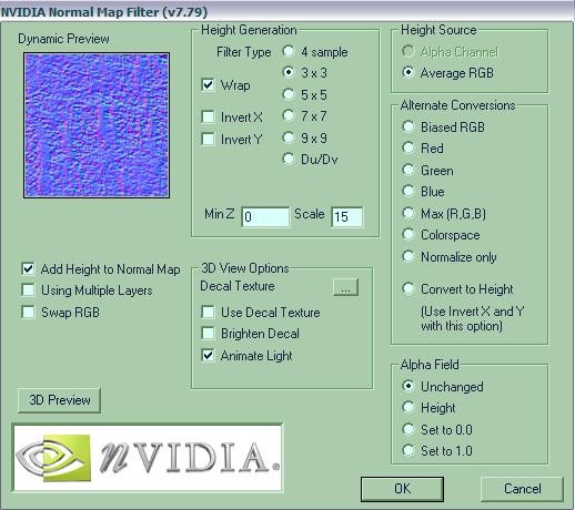
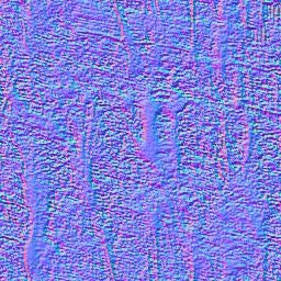
A new tab will come up, the NormMap filter interface: configure it as in the image below:
Then apply it:
Ok some explanation:
Filter type defines the size of the pixel depth. Scale defines the pixel depth. Average Source defines the source from which the filter takes the colours to be normal mapped.
Other options seems not to work in ArmA.
Point 2: Now that the normal map texture has been done, save it as tex1_nohq.paa (using PAAplug, and leaving all the options as they are) Then cut and paste the file into BOX folder.
You'll notice that if you'll try to open the texture with texView 2, the program will crash: don't worry, it's not a problem.
Creating Specular Map
Point 3: let's create the Specular map. Open texView 2, then tex1_co.paa, and go to Edit → Filter… and write in the box (repacing the existing code):
	sp = 10;
	p = src pixel [u,v];
	x = 1 - green p;
	y = green p * ((sp * blue p + 1) / (sp + 1));
	c = color[x,y,blue p,1];
Basically, this code is a bit difficult to understand. But…
sp: specular.
p: pixel.
x: X axis.
y: Y axis.
c: combined color.
This is what I understood so far Now save the new obtained texture as tex1_smdi.paa
Why did we save it with _smdi.paa extension? It's easy, cause in TexView 2, this extension means: optimised specular map for better bitdepth
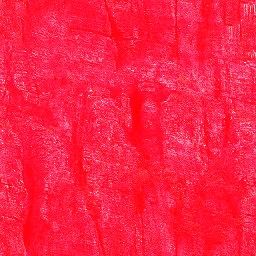
You should obtain something like this:
with this particular red tone applied. Copy and paste the file into BOX folder (as for all files). Now textures creation is completed. We must proceed to configure the model, to have it ingame!
Configuring the model
Open your text editor, and write in it:
#define ReadAndWrite 0
#define ReadAndCreate 1
#define ReadOnly 2
#define ReadOnlyVerified 3

#define private 0
#define protected 1
#define public 2

#define true 1
#define false 0

#define TEast 0
#define TWest 1
#define TGuerrila 2
#define TCivilian 3
#define TSideUnknown 4
#define TEnemy 5
#define TFriendly 6
#define TLogic 7

class CfgPatches
{
	class Linker_test1
	{
		units[] = {"BOX_BOX"};
		weapons[] = {};
		requiredVersion = 0.1;
		requiredAddons[] = {};
	};
};

class cfgVehicleClasses
{
	class Simple_box_class
	{
		displayName = "SIMPLE BOX";
	};
};

class CfgDestroy
{
	class BuildingHit
	{
		sound[] = {};
	};
};

class CfgTextureToMaterial
{
	class BOX_material
	{
		textures[] = {"BOX\tex1_co.paa"};
		material = "#BOX_material";
	};
};

class CfgMaterials
{
	class BOX_material
	{
		ambient[] = {1.0, 1.0, 1.0, 1.0};
		diffuse[] = {0.0, 0.0, 0.0, 1.0};
		forcedDiffuse[] = {0.0, 0.0, 0.0, 1.0};
		emmisive[] = {0.0, 0.0, 0.0, 1.0};
		specular[] = {0.0, 0.0, 0.0, 1.0};
		specularPower = 0.0;
		PixelShaderID = "NormalMapDetailSpecularMap";
		VertexShaderID = "NormalMap";

		class Stage1
		{
			texture = "BOX\tex1_nohq.paa";
			uvSource = "tex";
			class uvTransform
			{
				aside[] = {1.0, 0.0, 0.0};
				up[] = {0.0, 1.0, 0.0};
				dir[] = {0.0, 0.0, 0.0};
				pos[] = {0.0, 0.0, 0.0};
			};
		};

		class Stage2
		{
			texture = "BOX\tex1_co.paa";
			uvSource = "tex";
			class uvTransform
			{
				aside[] = {1.0, 0.0, 0.0};
				up[] = {0.0, 1.0, 0.0};
				dir[] = {0.0, 0.0, 0.0};
				pos[] = {0.0, 0.0, 0.0};
			};
		};

		class Stage3
		{
			texture = "BOX\tex1_smdi.paa";
			uvSource = "tex";
			class uvTransform
			{
				aside[] = {1.0, 0.0, 0.0};
				up[] = {0.0, 1.0, 0.0};
				dir[] = {0.0, 0.0, 0.0};
				pos[] = {0.0, 0.0, 0.0};

			};
		};

	};
};

class CfgVehicles
{
	class Thing;
	class Building;
	class Strategic;
	class NonStrategic : Building
	{
		class DestructionEffects;
	};
	class HouseBase;
	class Land_VASICore;
	class House : HouseBase
	{
		class DestructionEffects;
	};
	class BOX_BOX : House
	{
		scope = public;
		simulation = "house";
		vehicleClass = "Simple_box_class";
		model = "\BOX\box.p3d";
		displayName = "Simple box!";
	};
};
Ok, some explanation:
class CfgTextureToMaterial
{
	class BOX_material
	{
		textures[] = {"BOX\tex1_co.paa"};
		material = "#BOX_material";
	};
};
This part of the config is needed to define the conversion of the textures to the material defined in the CfgMaterials class.
	class BOX_material
	{
		ambient[] = {1.0, 1.0, 1.0, 1.0};
		diffuse[] = {0.0, 0.0, 0.0, 1.0};
		forcedDiffuse[] = {0.0, 0.0, 0.0, 1.0};
		emmisive[] = {0.0, 0.0, 0.0, 1.0};
		specular[] = {0.0, 0.0, 0.0, 1.0};
		specularPower = 0.0;
		PixelShaderID = "NormalMapDetailSpecularMap";
		VertexShaderID = "NormalMap";
	};
To understand the use of numbers in this class, go to RVMAT file. I don't want to repeat what is written there.
	class Stage1
	{
		texture = "BOX\tex1_nohq.paa";
		uvSource = "tex";
		class uvTransform
		{
			aside[] = {1.0, 0.0, 0.0};
			up[] = {0.0, 1.0, 0.0};
			dir[] = {0.0, 0.0, 0.0};
			pos[] = {0.0, 0.0, 0.0};
		};
	};
	class Stage2
	{
		texture = "BOX\tex1_co.paa";
		uvSource = "tex";
		class uvTransform
		{
			aside[] = {1.0, 0.0, 0.0};
			up[] = {0.0, 1.0, 0.0};
			dir[] = {0.0, 0.0, 0.0};
			pos[] = {0.0, 0.0, 0.0};
		};
	};
	class Stage3
	{
		texture = "BOX\tex1_smdi.paa";
		uvSource = "tex";
		class uvTransform
		{
			aside[] = {1.0, 0.0, 0.0};
			up[] = {0.0, 1.0, 0.0};
			dir[] = {0.0, 0.0, 0.0};
			pos[] = {0.0, 0.0, 0.0};
		};
	};
This part is needed to define the stages of a single texture: in our case is tex1_co.paa. You have to add 3 stages for a single texture, because we have 3 different files: the nohq one, and the smdi one.
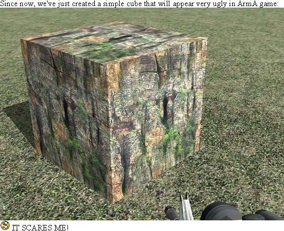
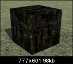
With this simple config we will have this result: But, if we play with specular and specularpower, defining them in this way:
	specular[] = {0.2, 0.3, 0.3, 0.6};
	//{0.2, 0.3, 0.3, 0.6};
	specularPower = 10.0;
Ok, this tutorial is enough to understand the basis of Normal and Specular mapping in Armed Assault.
First time i found it difficult, but now I know it isn't! You only have to sit in front of your PC, and try, try, try… I hope this tutorial helps!
Cheers all Linker Split
Notes
This tutorial was written by Linker Split. Please note that this tutorial is now out-dated regarding the config.cpp materials as we can place the rvmat file from O2 directly.
