Table of Contents
OFP Brsseb 3D Modeling Tutorial
OFP Forum, OFP Home, OFP File Formats, OFP Tools, OFP Missions, OFP 3D Modeling, OFP Terrain
Operation Flashpoint (OFP) aka ArmA: Cold War Assault (CWA)
Lesson 4: Creating your first Helicopter
Creating your first Helicopter by Brsseb
Preparing for the lesson
Hello, and welcome back to yet another lesson. This time you get to make your very own helicopter. And if you`ve followed the previous lesson this should be a walk in the park. Therefore Im not going to be that step-by-step as I was in the beginning lessons (aka wont repeat over and over how to do simple stuff like texturing, naming selections and LODs and stuff). But dont worry, we are keeping things simple as usual. I will provide a simple model and textures and I will guide you trough each step in getting the heli airborne.
So, what skills do you need then. Lets see:
- OFP (daahhh), O2 and Bulldozer
- Basic understanding of the O2 interface
- Having fully understud stuff from lesson1 (like creating LODs, selections etc)
- Also, if you made it through lesson 2, this should be an easy lesson.
- PBOTool and TexView
Ok, thats the most important things. Now move on and have a look at the model we are going to turn in into a chopper.
The basic model
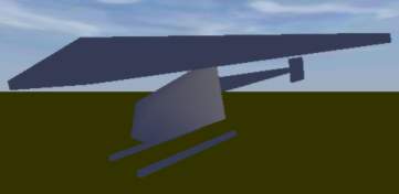
So lets have a look at our model. As Ive told earlier, this is a VERY simple model and Im not wasting valuable 3d model time making an accurate 3d model of a heli for this simple lesson. So I just stripped the model from lesson 2 for wheels and spolders, added a tail section, skids and rotors. Also some changes to the geometry LOD to go with the new model in the main LOD:
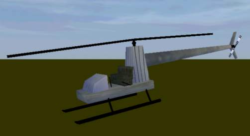 The new model view from Bulldozer
Yes, the lesson example models keep getting uglier and uglier, I know. But you`ll learn from it, thats the main point. Lets get started:
- Download the example model with textures and extras Brsseb_lesson4_start.rar from bottom of this page.
- The files go in a folder named “firstheli” in the dir where Bulldozer is installed
Then fire up o2 and Bulldozer and check out the model. Its all very basic stuff and you can create such a model with the simple stuff learned in lesson 1 and lesson 2. Just blocks or cylinders with textures on them. In the geo lod key parts have been modelled and the whole thing has been applied wheight to. All thinks that should be familiar to you now.
Now, lets gets started, we`ve got a long journey ahead.
Fire Geometry
Im going to walk you trough all the normal LODs fround in a heli addon and we will start with Fire Geometry. Fire Geometry is something that most addons have, but for simple reasons i havent talked about it in the previous lessons. Fire Geo is much like “normal” Geometry, but where Geomery is used for collision detection (addon bumping into other objects or terrain), Fire geometry is used for checking if it is hit by a bullet, grenade, rocket etc.
So without Fire Geo, bullets could just pass trough the addon without hitting the model? Well, not true. Because if ofp cant find Fire Geometry, is automatically used normal Geometry instead. Great, isnt it? So we dont need Fire geo then? Yes, we need it. Notice that the structures (or components, if you like) in our model is very blocky and dont fit good to their actual LOD parts in “0.000”; aka the main body structure with bottom plate, seats, front panel, etc is just a big block in the geo lod. That means that you can shoot a bullet close to, but not directly on, the airframe ingame and still hit the helicopter. And thats a bit unreal, isnt it?
But why not make the geo lod more detailed, then? The fact is that more detail in the geo department means more load on the CPU. Remember that collision detection is something done all the time ingame, while checking for firehits are done only when something is fired! That way we can have a low-detailed model for the Geometry lod and a higher detail model for the Fire Geometry. The bottom line is that Geometry detail is more expensive than Fire Geometry.
If you dont understod all the above, then dont care much about it. Its not that important to understand, right now you just do what I say and all will be well:). The content in the Fire Geo lod will be similar to the Geometry LOD but with more detail. To avoid creating to much (and since our main model is so simple anyway), we will use some parts from the main model and some from our Geo lod (sort of meeting eachouther on the half-way, if you like).
- Fire up 02 and open our helimodel
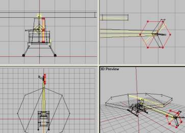
- Go to our main lod (0.000) and hit F2. While holding down ctrl, drag around a vertex in each sturture and select all of the structures in the picture below. Make sure to get them all and just them (Dont forget the horizontal stabilizator on the tail).
- Hit Ctrl+C to copy the selected structures.
- Create a new LOD and change the type to “Fire Geometry”
- In the new LOD, hit Ctrl+V to paste the copied structues into that one.
- Now we need the tailboom. The one in “0.000” is too detailed, too much wasted CPU power, but the one in Geometry LOD will do just fine. So go to Geo LOD, select the Tailboom, Ctr+C, back to Fire Geo Lod and past it there. So far Fire Geometry should look like this:
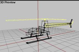
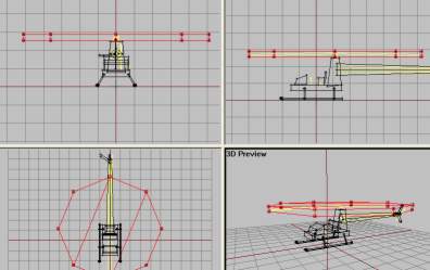
Now we need something to represent the two rotors. The ones in main LOD cant be used (tell you later..) and the ones in Geo is to much square-ish. They cover more that the places do for real. So we must make two flat cylinderstructues and we will start with the main rotor.
- Make Top view active and hit F8. Type 8 in the “Segemts Radius” and hit ok. Scale and move the cylinder inplace so that it looks like this:
- Now the cylinder for the tail rotor. Make sideview active, hit F8 and in the Segments Radius type 6. Hit ok
- Now scale and position it to cover the rotation area for the tail rotor like this:
Now basic Fire Geometry is almost done. We now have defined the areas that the ofp engine will use to check if our model is hit or not. But we need to do some fixes first. First of all, structures in Fire Geo cant have textures (why would they, its invisible!). And the parts you copied from “0.000” LOD have textures on them that we must remove. Remeber from lesson 1 we learned how to make sure that o2 got the right texture paths for our model? We used ctrl+LMB (doubleclick) the listed textures to autoselect all structures that had that texture, activated a view and hit “E”? if not, see last part of texturing in lesson 1 now.
You must do like in lesson 1 but instead of making sure that the path in the lower editbox is right, we delete it and hit apply, then OK. This will remove the texture from the selected structures. Do this prosess for all the listed textures in the Fire Geo untill all textures are gone. Also, when we copied the tail boom part from Geo LOD to the Fire Geo, we got its named selection with us. In Fire Geo, Select the named selection (called component04 I think) and delete it (RMB and delete).
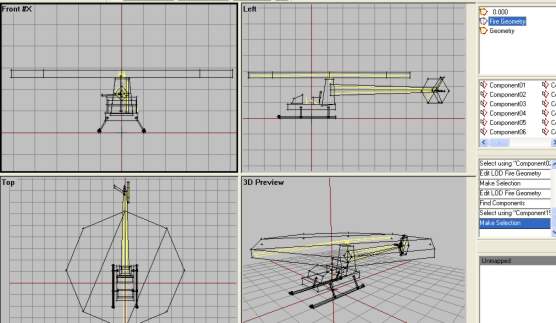
Like in Geometry LOD, all structures had a named selection for them, called Component01, 02 etc. We must have this in Fire Geo too. But instead of making them manually, we can make o2 do this automatically for us (why I wanted you to delete the Component04 for the tailboom to avoid o2 getting comfused). So, while in the Fire Geo LOD and no components selected, find “Structure→Topology→Find Components” from the menu. All parts will now be assigned a “ComponentXX”-selection (should be 15 in total).
Now we are done with the Fire Geo LOD. It should look like this now:
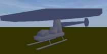 Bulldozer view, make sure all textures are gone
Now lets move on.
HitPoints LOD
In adition to having a Fire Geo LOD for knowing when the model is hit by gun fire, the ofp engine is capable of knowing WHAT parts are hit. It is the fueltank? The engine? That way we can have more realistic damages for our model. But how will the structures in HitPoints LOD look like? As you may think, it should be similar or near identical to the ones in the Fire Geometry. Usually addon makers have some differencen between the stuctures in Fire Geo and Hitpoints LOD, but its not important for this lesson. So we will just use structures from our Fire Geo LOD and make some new named selections. Lets move:
- Go to Fire Geo LOd and hit Ctrl+A to select everything in it. Then hit Ctrl+C to copy.
- Make a new LOD and change it to HitPoints from the property list. In this LOD, hit Ctrl+V to paste the structures in it.
- Now delete all the named selections (Component01, 02, 03 etc) so that there are no named selections in our HitPoints LOD. It will look like this afterwards:
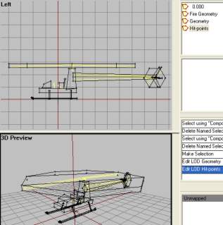 HitPoint LOD with no named selections
Now we must make some named selections or this LOD will have little use. Simply we tell ofp like what part is the engine, what is the main rotor, etc by selecting structures and creating named selections for them. There are lots of named selections that can be used in this LOD, but we will just consentrate on the most common ones:
- Elekronika: Eletronic systems.
- Motor: The engine itself.
- Mala vrtule: Tail rotor.
- Velka vrtule: Main rotor.
- Ocas: Tail Boom.
- Stabilizator: Horizontal tail fin
- palivo: Fuel tank
- Trup: Main fuselage
- svetlo L: Left light
- svetlo P: Right light
- Pilot: Pilot
- Cargo: Passenger
So lets get to work:
- Using F2, select the block in front of the seats and create a selection for it called “elekronica”.
- Next select the Tall block behind the seats (the one holding the main rotor up) and give it a selection called “motor”.
- Then select the tail rotor cylinder and name it “mala vrtule”.
- Select main rotor cylinder and call it “velka vrtule”
- Select the tail boom and the vertical stabilizator, leaving the horizontal one out. Name them “ocas”.
- Select the horizontal stabilizator and call it “stabilizator”.
- Select the seat section and call it “palivo” (yes, they sit on the fuel tank).
- Select the bottom plate, and all 6 parts of the landing gear and call them “trup”.
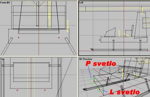
Now for the last parts of the named selection list above, we need to add some vertices (well, we have used all of our structures now, havent we). We need a vertex sympolising the pilot, one for the passenger and two at the front of the model representing the headlight positions (yes, our heli will have working lights!).
- In side view, place a vertex just in front of the bottom plate.
- In front view, make a copy of it (shift+move with x-axis locked) and place them equal distances from the centerline. Then select each one and call them “L svetlo” and “P svetlo”. Like this:
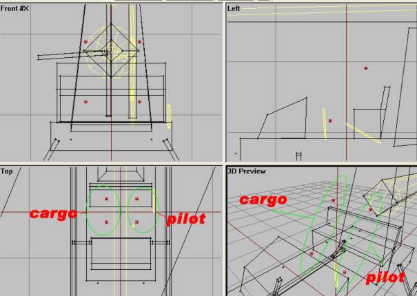
- Then the last two ones, Pilot and Cargo (Passenger). Place 4 vertices in the seatarea like in the next picture. Each position has two vertrices (greater chance of hitting the pilot or passenger).
Phew, lots of names there. But now we are done with HitPoints LOD. Continue…
LandContact LOD
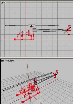
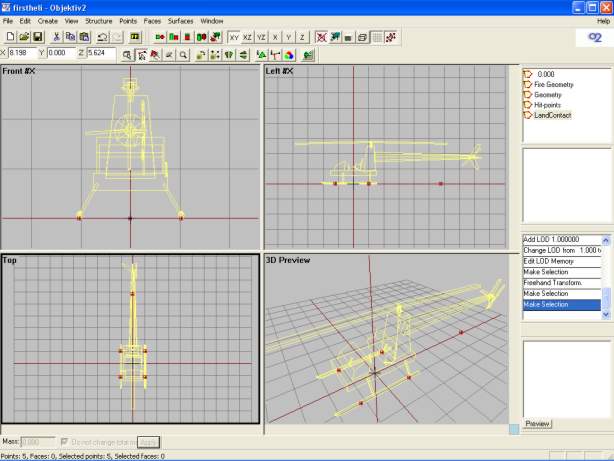
Next LOD out is LandContact and its an easy one. The name gives away its function so we`ll just do this without too much talk. The idea is to place 5 vertices beneath the heli, two under each landing gear and a fifth one at the rear center (to make it harder for the heli to tip backwards in bad landings, I think). Its very easy, just 5 vertrices on the same plane (aka use x-axis locking when crag_copying them). Its very easy to do and similar to the 4 vertices we put under the wheels of the car in lesson 2. Make a new LOD and make it “LandContact” and start placing vertrices. Here is a picture of the final placements.
Pretty easy, huh? And no named selections needed whatsoever. Strange that, but in all the addons Ive seen; no named selections for the LandContact LOD.
Next one then.
Memory LOD
And here we are back with another episode of a “Chopper is born” here on Discovery, Im Mark Eavens and today we`re….ehh..oh, never mind. Watch the show, people!
Ok, ready for the “Big One”? This is the most important LOD (I think). Its got lots of different named vertrices. If you followed all the lessons you know that here is where we place stuff like in and out positions for the player, axis-definitions (like for the steeringwheel in lesson 2) and alot of other things. But we are soon ready to take off so dont give up now.
Here is a list of all the named selections we need:
- cerveny pozicni blik: Red positional blinker
- zeleny pozicni blik: Green positional blinker
- l svetlo: Left light
- p svetlo: Right light
- konec l svetla: Left light end
- konec p svetla: Right light end
- mala osa: Tail rotor axis
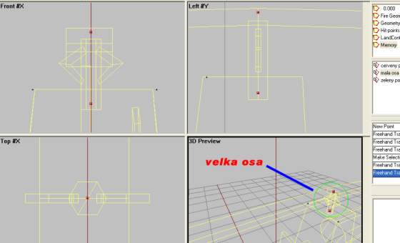
- velka osa: Main rotor axis
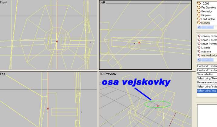
- osa vejskovky: Axis of elevator (horizontal stabilizer)
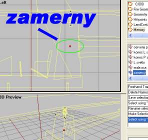
- zamerny: Aiming point/line of sight
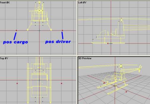
- pos driver: Pilot in/out position
- pos cargo: Passenger in/out position
So lets get to work.
- Create a new lod and change it to Memory LOD. We will start on the top of the list above.
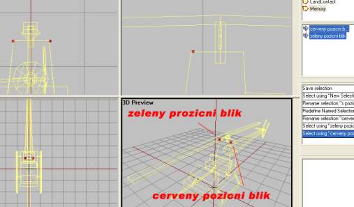
- Place two vertices on each side of the heli and make them “cerveny pozicni blik” and “zeleny pozicni blik”, like the picture below.
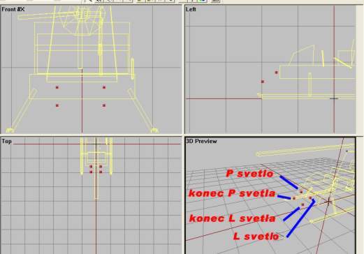
- Place four vertices in the front position to indicate light position (two lights, start and end). Like this:
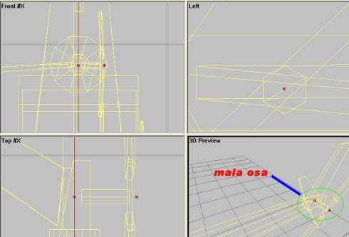
- Next is the Tail rotor axis, “mala osa”. Place two vertices a distance from each other like in picture below. Make sure its in the center of the tailrotoraxis in the original model LOD (“0.000”) and that the axis the lines create are parallell to the ground. Select both vertrices and name them “mala osa”.
- Same for the main rotor axis, “velka osa”. Two vertrices placed directly on top of each other in sideview and in the center of the actual helicopter model`s rotorshaft. Like this:
- Axis for the horizontal stabilizator, named “osa vejskovky”, is just a single vertex placed like in this, in the center of the model in the tail section. Insert it from sideview to make it appear in the center when viewed from frontview.
- And for the line of sight, just put a single vertex inside the engineblock and name ot “zamerny”. Insert it from sideview to make it appear in the center when viewed from frontview.
- And finally two vertrices that should sound familiar to you from lesson 2, the entering position for the “pos driver” and “pos cargo”. Just like in lesson 2, here it is:
…And there we are done with Memory LOD. Move on
Preparing the main model LOD "0.000"
Ok, we are not creating a new LOD this time because we need to make some changes to the original LOD, “0.000”, to make it look good while flying. We have to make some named selections and even apply a texture or two (!), but nothing too scarry. Soon done now, promise.
As usual, a list of all the named selections we will make. There are of course more, but we only need these for our tutorial model:
- vejskovka: Horizontal stabilizator
- mala vrtule: Entire Tail rotor
- mala vrtule blur: Tail rotor face with blur texture
- mala vrtule staticka: Tail rotor, static version.
- mala vrtule textura: Tail rotor, only blur texture
- velka vrtule: Entire Main rotor
- velka vrtule blur: Main rotor face with blur texture
- velka vrtule staticka: Main rotor, static version.
- velka vrtule textura: Main rotor, only blur texture
In addition to that we will have two proxys, one for the pilot and one for the passenger.
Lets get going, shall we?
- Go to “0.000” LOD and use F2 to select the horizontal stabilizator on the tail. Name it “vejskovka”.
- Now the proxys; there were two proxy models from the demo in the zip you got from the beginning of the lesson. Like in lesson 2, put them in the data3d folder in Bulldozer. If you dont know what proxys is, see lesson 2.
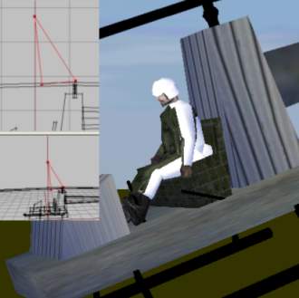
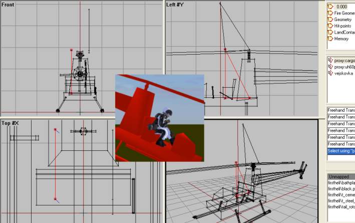
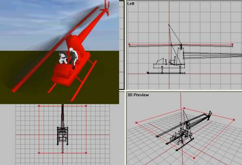
- Just as in lesson 2, choose insert proxys from the menu. We will insert one for the “pilot” and one for “cargo” (passenger), move them into place and use Bulldozer to see if the proxys are well placed in the model. The one for the Pilot is called “uh60pilot” and the other is called “cargo”. Use these names in the “Insert Proxy Dialog”. Here are some shots from the prosess:
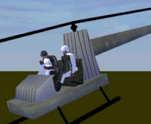 The final result. Dont worry if they dont look to good, my model dont fit these proxys perfectly (I had to rotate the pilot abit forward just to get his feet on the floor and the cargo proxy sits a bit inside the seat). But looks isnt too relevant for this tutorial model
Great, proxys are done. Nice. Now for the rest of the named selections from the list above. But first we need to do some texturing Im affraid. If you have looked on the textures in the zip, you`ll see that when the rotors are spinning at top speed, the rotormodel is replaced with a blured texture rotating at slow speed to make it look like its the rotor spinning at high rpm. Yes, its all a fraud, Im affraid. But it will do. Lets do this:
- Go to top view, click create→plane. Set both X and Y size to 10 and hit OK. Just after hitting OK, hit F6 to make a “double faced face” of the new plane. Now deselect the plane and the reselect it (you must do this, because after hitting F6 only one side of the plane is selected). Now you have a double sided plane that we can texture.
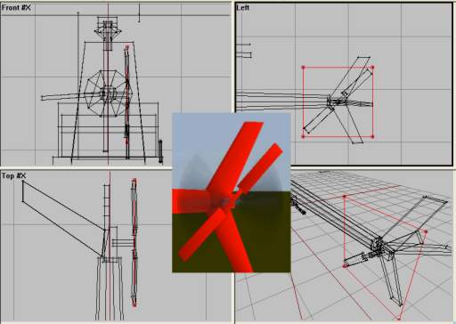
- Hit A and load the texture named “rotorblur.paa”. Draw it around the plane and apply it with “B”. Then move the plane so that it lies in the rotation path of the rotor blades, like this.
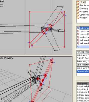
- Now we will use a copy of the same textures plane for the tail rotor. So select the main rotor with F2 and hit Ctrl+C to copy. Paste the new copy, scale and rotate it so that it looks like this:
Now listen very carefully and follow my next instructions to the point:
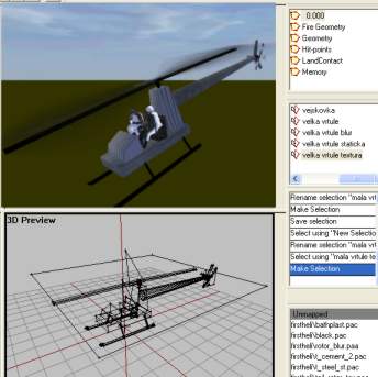
- Using F2, Ctrl and LMB, select the main rotor textured plane, the main rotor blades, the main rotorshaft and its two arms. Name that selection “velka vrtule”.
- Now select only the main rotor textured plane and name it “velka vrtule blur”.
- Select only the main rotor blades and call it “velka vrtule staticka”.
- Now select only the main rotor textured plane (again, I know) and name it “velka vrtule textura” (not sure if this is mandatory, but do it anyway to be on the safe side).
- Now for the tail rotor (any its the same think only with “mala” instead of “velka”, but here it goes anyway).
- Select the tail rotor textured plane, tail rotor blades, middle section and the tail rotor shaft. Name it “mala vrtule”
- Select only the textured tail plane and name it “mala vrtule blur”
- Select the two tailrotorblades and the middle section and call those 3 structures “mala vrtule staticka”.
- Select only the textured tail plane (again) and call it “mala vrtule textura”
And we are about 90% done with our heli right now! I promise.
"View Cargo" and "View Pilot" LODs
Ok, just this last bit and we are done. But there is one more think I havent talked about in my lessons so far and thats the optional LODs called “View Pilot” and “View Cargo”. You see, when you are the pilot or cargo looking in firstpersonview in the heli, you dont see the whole model. You see the front of the heli, cockpit detail, maybe the skids and parts of the spinning rotor. But there are thinks that you newer see, like the main rotor shaft parts and absolute nothing from the tail section. Problem is that if the computer is to draw the entre model even when you are unable to see the rear section of the model in Firstperson view, the CPU is wasting its power.
This has another side too. Sometimes we want very detailed cockpits and the details may be hard to spot or notice from 3rdperson/external view. So to make externalview go faster (more frames per second, FPS, that is), we leave out some details from the normal LODs (“0.000”) and increase detail in “View Pilot/Cargo” LODs.
So basically we make new lods named “View Pilot” and “View Cargo” which contains only the stuff from “0.000” that is visible by the pilot/cargo. This is how:
- Go to “0.000” LOD and select all (Ctrl+A), hit Ctrl+C to copy everything.
- Make a new LOD and change it to “View Pilot”. In that one, paste (Ctrl+V) the copied stuff there.
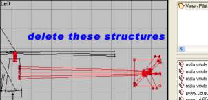
- Now try to think about what detalis are not viewable from the cockpit. We will delete them. Here is my list: tailboom and entire tailseciton and main rotor shaft with two arms (abit unsure on the landinggear, so I let it stay there). You dont have to delete the named selections even though you have deleted the structure that they are pointing to. Here is what I deleted and how it looked afterwards:
- Also we need an LOD for the Cargo proxy, the passenger. First in the “View Pilot” LOD, select and copy everything. Make a new LOD and call it “View Cargo” and paste into that one so that “View Pilot” and “View Cargo” LOD are identical. They are the same since what the passenger see is the same as the pilot can see.
 How the “View Pilot” and “View Cargo” should look like in Bulldozer after deleting some structures
Ok, thats that then. One last thing though. When I made my first chopper model, I had a problem. Scenery behind the model started to flicker or disapear for no reason. I posted the problem on the forums and got an answer on how to solve it; making a LOD named “View Geometry” that had the same content as the “0.000” LOD. I cant say I understand why this would work, but it did anyway. So you need one too. Simple, go to “0.000”, select and copy all. Make a new LOD and change it to “View Geometry”. Paste it all in there. Thats it. Nothing more.
Guess what, thats the last of the LOD stuff. We are now done with our heli model and its ready to fly. But first, a look at the configfile. Next!
The config file
Getting configfiles to work the way you want them has usually involves some serious OFP crashes, some loud screaming and shouting at the computer combined with a scarifise of a holy goat to the Dark Lord himself in hope for BIS to release a configfile editor with a build-in debugger. In the meantime we are usually stuck with good old notepad and basic C++ programming skills. So I am not going to tell you how to make a configfile, I`ll just talk about the one Ive used for this tutorial and leave it up to you go understand how it does its magic.
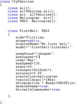 The most interresting part of the configfile
As you can see there are many known features attributes to you here, like the “model=”, “transportSoldier” and “displayname” (if not, see lesson 1 and 2). I have used the UH60 class to get the basic features that a chopper have, removed the gunner (hasGunner=0), slowed it down (maxSpeed=130), only one passenger (transportSoldier=1) and made it a civilian aircraft (TCivilian, meaning “Type Civilian). If I had not inherited the Uh60 class, I would have to add much more attributes that would just be confusing right now for the newbie.
Note: This configfile was tested on v1.75 and upwards. To make the heli work properly with 1.46 and lower, you may have to delete the class named CfgModels in the configfile. Just delete that section and you will be fine.
Ok, enough talk. Lets get this thing in the air, then.
Final
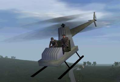
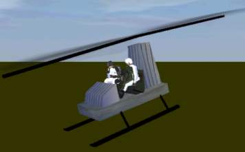
Ok, then. Ready to fly it? Then just fire up PBOTool, compress the folder and save it as “firstheli.pbo” in your OFP Addon folder. You`ll find it under Empty→Air→“My First heli” in the editor. Go on and test it, both in the day and night to see if the lights work properly. Here are some shots of it ingame:
And you are done, soldier. Feel proud because you have just build your first working chopper for ofp!
Some may feel abit down right now, maybe some hoping for a complete guide to making working cockpit instruments, custom sound or loaded with weapons. Then remember that this is a simple tutorial and the goal was to get the basics in making an heli for ofp. And I have told you the basics, like what LODs are good to have, the most common named selections and a few hints and tips here and there.
PS: You may have noticed that the chopper can fire rockets (in a rather strange way). This is because we used the UH60 class and that heli has rockets. So now you can use what you have learned and make some rocket pods for the heli, then in Memory LOD place a vertex under each rocket pod and name them “L Raketa” and “P Raketa” to make the rockets fire from there positions instead of the basic model-center that is standard. But its up to you. Its great practice anyway.
As usual you can download the finished model here. Any feedback, questions, bugreports goes in the usual mailbox, brsseb@hotmail.com (or live via MSN).
Good night folks! And happy heli-ing!
Download OFP.Brsseb_Lesson/ Torrent Magnet from below:
magnet:?xt=urn:btih:40aac3407210ddb8ffcee06cdb009c0b099ccdce&xt=urn:btmh:122046986f756bcebf9744dc9f81bc3fc736a54e164113ec62e18c827a4a06271364&dn=OFP.Brsseb_Lesson&tr=udp%3a%2f%2ftracker.opentrackr.org%3a1337%2fannounce&tr=udp%3a%2f%2ftracker.openbittorrent.com%3a6969%2fannounce
Notes
This tutorial was written by Brsseb in ofp.gamepark.cz/_hosted/brsseb/, it was posted here with his permissions, thank you Brsseb!

