Table of Contents
Falcon 4 HOWTO Skin Making Overview
Falcon 4.0 Forum, Falcon 4 Home, Falcon 4 Campaign, Falcon 4 Cockpits, Falcon 4 Database, Falcon 4 File Formats, Falcon 4 SRTM Terrain, Falcon 4 Terrain, Falcon 4 Textures, Falcon 4 Tools
by Zaggy
To help people wanting to go further than just editing existing skins, i will run through the basic steps i use to create a skin. This is by no means the definitive guide or the expert method; quite the contrary. Graphically creating something such as a skin, is a task that can be achieved by a variety of methods, that can vary due to such things as graphics background, type of skin, resolution of skin as well as the methodology.
But lets get to it… the below guides are based upon LOD Editor 5.1.0 and Photoshop 7.0.1, but should be applicable for most other versions of each application.
Wire frames
The first thing you will need are your wire frames. These are essentially blank skins, that feature only the polygons of the model, unwrapped and layed flat. This sets out the shapes that we have to now skin.

You can export these directly from LOD Editor, for any model that is in the database. I also export the model itself to a file, and place all the wire frames as well as the model lod file into a new folder. This way i keep everything to do with my current project separate from my working F4 install.
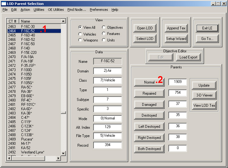
Once you have LOD Editor on your PC, start it up, and find the object you wish to skin from the list of objects on the left hand side. Our example, the F-16CJ-52 is 2462 in the list. Click on the object (1). Now on the right hand side of the main LE window, you'll see a section titled 'Parents'. Inside this section we need to click on the [Normal] button (2), which will open a new window titled 'LOD Parent Data'.

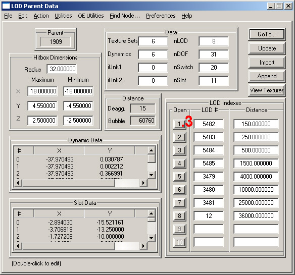
Again we look to lower right hand side to the 'LOD Indexes' section, where we click on the [1] button (3), to again open a new window, this time called 'LOD Data'.
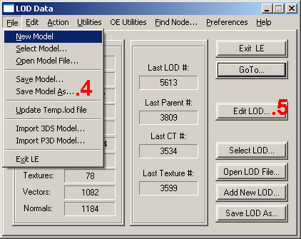
At this point we can export the model by simply clicking File → Save Model As… (4) then entering in a filename (such as F16C.lod) and choosing where to save the model to. Once saved, we find ourselves still at the 'LOD Data' screen.

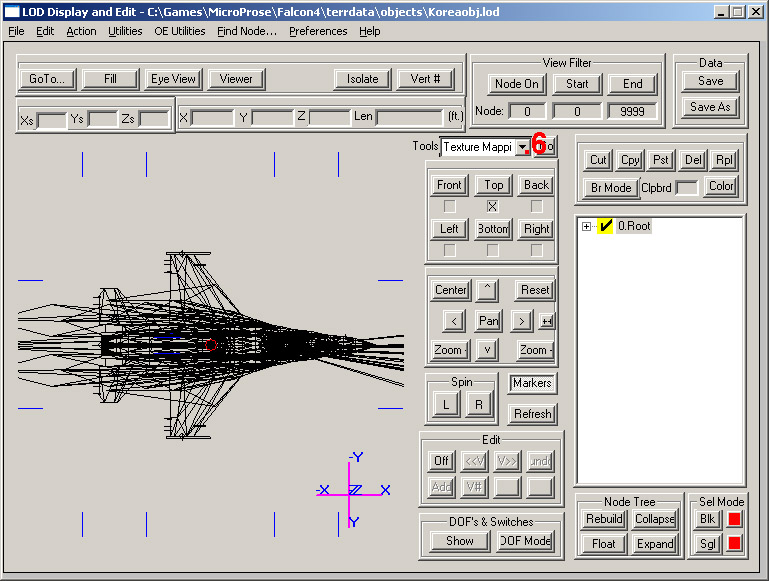
To also export the textures, we continue via the [Edit LOD…] (5) button, which again brings us to a new window, called 'LOD Display and Edit'. This screen shows us a wire frame image of our chosen model, but this should not concern you.
To the right of the model, you should find a small drop down, titled 'Tools'. We need to select the 'Texture mapping' (6) option, then click [OK] at the 'No texture nodes' dialogue that pops up.

Now we are at the 'Texture Mapping' screen. Again to the right, below the first drop down, click on [Hide Texture], (7) then just to the right again, check the Nodes Show All (8) option. Back to the Select Texture drop down, we now work through each texture, clicking on the texture number in the drop down, then on the [Export Map] (9) button, giving the texture a file name (which should just be the texture number, followed by .bmp), and then choosing to save at either 512×512 or 1024×1024.

REMEMBER, some models have multiple sets of skins, therefore the Select Texture drop down will have MANY textures. Note the texture number of the first texture. It will be something like '0[2043]'. Once you have worked through the list of textures and come to, for example, '13[2043]', you have exported all the wire frames you need.
Sound complex? well i guess it is, but once you have done this once or twice, it really becomes quite simple. A quick word of warning tho, back up your KoreaObj directory before you start, if this is your first time using LOD Editor. LE can destroy you object Database if you really screw up! :)
Mapping
Now, you should have a folder with a bunch of numbered .BMP's and a .LOD model file in it. I recommend backing up all the BMP's to a sub folder before we begin. In Photoshop, open all your newly exported .BMP's and convert them to RGB files. Now, you can work through the files one by one or jump in and try and do all them at once, the choice is yours. Label the parts of the wire frame you can identify or quickly paint them a certain color or label them with numbers, so we can start to identify the part. Now whilst we aren't, in the strictest sense of the term, Mapping, as it applies to modeling, we are 'mapping out what part belongs where', for our skins.
Check you have it right by saving the files as TextureNumber.bmp (I recommend you save the file as a PSD first, the wire frame will be the lowest layer, the put your text/numbers/colors on a second layer), then open LE again, select Utilities → Model Viewer - By File, navigate to your folder containing the model and your skins, click open and you should now find yourself seeing the 3D model skinned in the labeled wire frames you have just made. Hitting the [space] bar will bring you a control menu that can help you 'de-clutter' the model. I also HIGHLY recommend you read the 'OpenGLLOD.txt' read me that will be found in the LE folder. This file tells you all about the Menu as well as the key options.
This is probably the hardest, and at times, most frustrating part of the whole thing! My method normally is start with the big objects you can identify, create a basic skin for the a/c, then come back and fire the details out as you reach them. Now that you've figured out what shapes are what parts, you can get down to actually making the skin resemble the a/c in question.
Panels and Paint
Now i know what the parts are, i will paint all the shapes (typically JUST the external parts first) one of the camo colors and extend this coverage 2-3 pixels beyond the limit of the wire frame shape (normally i will select the shape, then expand the selection by 2-3 pixels (Select → Modify → Expand). The just fill the selection area with the color. Then again using LE, view the model as described before. HINT, if the leave the Model Viewer open, you can view your changes as soon as you save them to a BMP file (save as a 24Bit BMP), by simply hitting the [y] key in the Model Viewer.

Next I will track down as many line drawings of the a/c as possible. The best ones are Scale multiview drawings, that modelers will know so well, that show all the panel lines. These will be scanned in at a res that makes them a little larger than the corresponding texture wire frames are. Desaturate these graphics files (Image → Adjust → Desaturate) then using the Curves (Image → Adjust → Curves) tool, clean up the graphic by making the lighter shades 'more white' and the darker shades 'more black'. Save these files. Now, to create panel lines, we simply copy and paste these line drawings into out skin files, scaling them to fit, and in the layers window, changing the Layer Type (see image) from Normal to Multiply.
Once the panel lines are sorted, i will then start to paint the camo pattern, using the panel lines and viewing with the LE Model Viewer to ensure the patterns line up neatly. Once this is all conquered, the weathering begins.
Weathering
This is the section that is most open to personal preference and technique. There is no feasible way of going through EVERY technique I know of and use, as that would take many, many days for me to type and prepare. Instead I will give a breif overview of SOME techniques; the ones i feel provide the best basis for building upon, and the ones that may encompass several simple techniques at once. The below image is a small sample of these techniques.

As you can see in the above image, fitting the Panel Lines, and setting the Layer Type to Multiply, will produce what we see above, as labeled Camo Colors & Panel Lines. First thing i normally do once i have fitted the panel lines and start weathering is to make a copy of the panel lines, then using Filter → Blur → Gaussian Blur (and a setting between 7-20), blur these panel lines. The reduce their Opacity (the Opacity control is next to the Layer Type control, explained above) to around 40% or a setting where you don't instantly notice them. Then the original panel line layers will have their opacity reduced to about 20%. Your skin will now resemble the second layer, labeled Faded & Blurred Panel Lines. Save your files as BMP and view in LE Model Viewer, and you will instantly noticed the effect.

The next technique used above, uses the same Layer Type control, but this time we are using the Brush Tool. Create a new layer (SHIFT + CTRL + N or click once on the new layer icon, at the bottom of the Layers windows, next to the Bin), and on this layer, start to paint with a soft edged brush or airbrush. You can change the opacity and flow with the brush tool options (along the top of the screen in Photoshop 7.0) if you wish, to gain a bit more control, as i do. I use two colors mostly, each on a separate layer. One layer is black, and one layer is white. Pictured below, you will see the spine of the F-16 skin so far. The first half shows the two layers, one black and one white (they aren't as intense as normal, as I had the flow lowered to around 10-20%) at their full opacity. The 'shine' and 'shadow' is used to give the panels some 'depth' and curvature. In the second half, those layers have had their opacities reduced to around 10-15%; noticeable, but not blindingly obvious.

When starting to weather a skin, as above, subtle is the way to go. If you want it to be more obvious later, just come back and alter the opacity of the layer to a higher percentage.
This technique can also be used for muzzle flash stains, chaff/flare stains and most general weathering tasks. You can change the Brush Tool to a smaller diameter, or to a pencil type tool, a draw chipping paint onto a layer. You could use an Eraser Tool by coloring a layer over the top of your general camo color, then erasing bits here and there of that new layer, to create a patchy look. You could change the effectiveness of the eraser, so it only erases 10% of the pixel opacity at once. You can use the Smudge Tool to create streaks of oil or fluids.
The we can use filters on these layers we have created. Such as the Gaussian Blur tool (Filters → Blur → Gaussian Blur), or the Noise tool, to create varying degrees of pixelation (Filter → Noise → Add Noise… and check the Monochromatic check box) and the many other filters that exist.
But essentially what I'm getting at here is, build the weathering up in layers. Don't go combining layers, as often, as soon as you can no longer undo Merging Layers, you will realize you need to. And the second point here is, there are no right and wrong ways to do this stuff… Just guides. It all comes down to playing round with the various tools to see what you like the look of and understand how to use it best to achieve the look your after. Then you can always go to the web for Photoshop techniques sites and discussion groups, where you will find an almost infinite number of techniques and ideas, using layer masks and paths and all these other styles. But most of the time, the basics, as above, will get you through.
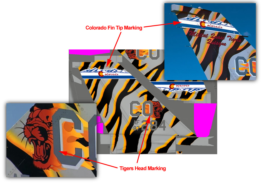
Markings
For me, this is the fun part. Turning an anonymous skin, into an individual a/c. The general rules here are the Marking go on top of the Camo Colors, but BELOW all other layers. So your layers might be, from top to bottom, Camo Color - MARKINGS - Panel Lines - Basic Weathering - Muzzle Flash and Oil Stains. Best advice here is, think how it works in real life. Dirt and grime cling to markings the same as they would the rest of the a/c, and panel lines will show through markings the same as they will show through the basic camo colored paints. Often, the markings will actually look dirtier than the a/c, the a/c is typically, dark, matte, grey colors, while the markings are often satin (a lot of markings these days are a mixture of satin and gloss paints and vinyl 'stickers') and colored, so the dirt and etc is more apparent on them.
How do we make these things? Trust me, its pretty hard to draw every individual roundel and marking, so again there are a few basics to follow. This is how I do things.
Photos
Photos can be used by erasing all the picture around the marking (either with the eraser or a the Lasso Tool), then scale, skew, rotate and distort it to the right shape (Edit → Transform → Scale/Skew/Distort/Rotate). Then we can just paste this into our skin.

Fonts
Of course its always easier to just type WW AF 91 800 than it is to draw it. So the way to go with all text and numerical markings, is to track down the FONT!

Decals
Hobbyists will know what Im talking about straight away. The decals you get with your model a/c. Just scan the decals in, then you have an almost perfect set of markings just waiting to cut out and pasted onto your skin!

Other
Then of course there are other sources. You can find unit badges on some squadron websites. Drawings on interest group sites (like modeling sites or aviation interest/photography). And if worst comes to worst, well, then you just start drawing and build the marking from its component shapes in Photoshop, Illustrator or some other graphics package!
Notes about Transparencies
Many skins now feature textures that are layered on top of other textures, so that we can customize unit markings a lot easier. For example, the F-16 skin contains all unit markings for the typical F-16, within the Tail texture. This texture has area's set aside for unit badges on the sides of the intakes, nose numbers as well as fuselage markings. Only part of these area's are shown on the model by way of using a reserved Transparency color, R255 G0 B255, or MAGENTA. The fact that DDS textures dont use Magenta as the reserved color any more does not negate this warning in anyway.

Anything you draw within these Magenta area's, make sure the edges have NO Anti-Aliasing. That is, the edges are not faded in anyway. Fading the edges will allow bits of magenta to bleed through, round the edges of the marking. So in the case of an Image, make sure the edges are not blurred or anti-aliased in any way. In the case of a font, ensure that the 'aa' is set to 'None', as seen in the image. Else what will happen is, when the font is rendered, the edges of the font will be Anti-Aliased (normally this would result in a smoother, better looking letter) and let the Magenta color beneath bleed through round the edges. This will prevent that.
Saving to DDS
Now so far to test our textures, we have simply saved them as 24Bit BMP's, and viewed them on the model, in LE - Model Viewer. To use these textures in Falcon 4.0 BMS, requires one more step; saving to a DDS format.
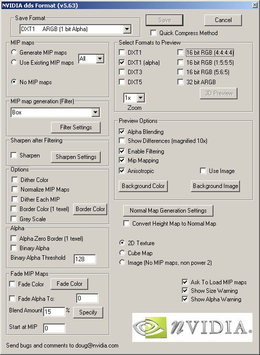
First thing you will need, is the nVidia DDS Plug-in for Photoshop. This can be downloaded from the nVidia site, and is also mirrored on this site. Once downloaded, unzip and simply copy it into your Photoshop plug-in directory (C:\Program Files\Adobe\Photoshop 7.0\Plug-Ins). If all is working properly, next time you start photoshop, it will automatically load, and will enable photoshop to now Open and Save in a variety of DDS formats. For the record, the DDS format we want to save is DXT1(Alpha) with No MIP Maps.
Now, we need to prepare our image. To do this, you need to flatten your image, in other words combine all the layers. You can do this with Layer → Flatten Image. If the resulting single layer is named Background, (this is a reserved name, meaning some functions do not work on it. The following is one of those cases!) simply rename it. In Photoshop 7.0, we just double click on the name in the layers window, and enter our new name or simply use the default name of Layer 0, which is normally what shows up.
Select the Magic Wand tool, set its properties to a Tolerance of 1 and make sure Anti-Aliased is UNCHECKED. Now using that tool, select all the area's of R255 G0 B255 (the Magenta 'Transparent' color, see the below example of 24bit BMP); you can add to your selected area by holding down the [Shift] key and clicking on the next area. You can also unselect an area by holding down the [Alt] key while you click. Once you have all the Magenta selected, clear it with Edit → Clear, alternatively cut it with Edit → Cut or [CTRL-X]. You should now be able to see Photoshop's Grey/White checkered background, indicating there is nothing present.

We are now ready to save, File → Save As… , select DDS from the drop down Format box, enter a filename (ideally the texture number) and click [Save]. The DDS dialogue box (see Image) now appears. the Important settings are Save Format = DXT1 ARGB (1 bit Alpha) and MIP maps = No MIP maps. You can choose to preview the texture in a variety of formats also, but pay attention to the DXT1(alpha) preview. The area's formerly of Magenta, should now be BLACK.
If all looks good, click on the [Save] button, and its done!
For textures without transparencies in them, the process is FAR easier. Its simply a case of Flattening the Image, and saving to DDS, using the same settings and outlined above.

To illustrate, below we have the end product, the DXT1(alpha) with BLACK area's of transparency, the 24Bit BMP, with the MAGENTA transparency area. The latter is used when skinning the model in LE - Model Viewer. When converting to DDS, it is this Magenta area that needs to be selected, then cut, before the texture can be saved.
BMS Installation
To install the DDS skins you've just made into BenchMarkSim (BMS), simply go to your ..\MicroProse\Falcon4\terrdata\objects\KoreaObj folder and BACK UP the files in there that share the same names as your newly created skins (eg, 3161.dds for an F-16CJ Tail). Its always good to back up, just in case the newer skins we install look crap, or you've gotten the filenames wrong, etc.
Now simply copy your NEW dds skins into the ..\MicroProse\Falcon4\terrdata\objects\KoreaObj folder. Start Falcon, and they should be there!