Table of Contents
OFP Level of Detail (LOD)
OFP Forum, OFP Home, OFP File Formats, OFP Tools, OFP Missions, OFP 3D Modeling, OFP Terrain
Operation Flashpoint (OFP) aka ArmA: Cold War Assault (CWA)
What's a LOD?
LOD means Level of Detail, and is a method of defining, via different variations of a model, how high or low the viewable quality of the model should be, and how it should interact with the environment.
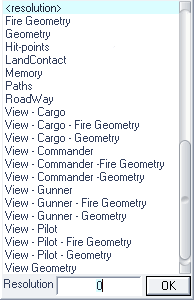
<resolution>
 Defines which model to use, depending on several, interdependent in-game conditions (view-distance, number of objects, video quality, CPU utilization, etc).
This LOD shouldn't contain any empty Named Selections which are used in animations or by the game engine (wheels, etc), as that might cause the game to crash once the LOD becomes active.
To demonstrate the complexity of the LOD selection, and the effect the resolution name has on LOD switching, a series of tests have been documented here: Resolution LOD Samples.
If all your LODs (or if you only have one) are high polygon count, then your model will cause CPU slowdowns.
Details
Resolution Level Of Detail's (LOD) are nice things that make detailed objects close, look not so detailed from far away.
VTE uses res lods of 0, 1, 2 and 4 for objects. Soldier models maybe 0.1, 0.5, 1, 2 about, for weapons even smaller. VTE weapons try to use 0, 0.7, 1.5, 2, 2.5, 3 resolution LODs.
Resolution LOD in size of 12.0 or larger is not displayed at all in OFP.
If faces are 50 or less, you only need a 0.0 resolution LOD.
Vertex is the point, face is the side.
BIS urges add-on makers to have a minimum of 5 LODs for objects. BIS themselves even use 6 LODs for bigger vehicles. If you have a highly detailed vehicle, you may want to use 7 LODs.
LOD A : ~7500 vertices
LOD B : ~5000 vertices
LOD C : ~2500 vertices
LOD D : ~1500 vertices
LOD E : ~700 vertices
LOD F : ~300 vertices
LOD G : ~100 vertices
BIS M2A2 model has the following resolution LODs:
LOD A (0.750): ~3400
LOD B (1.5): ~1900
LOD C (3): ~1100
LOD D (5): ~560
LOD E (7): ~375
LOD F (9): ~175
LOD 9 is the lowest level of detail by definition.
After some counting and comparing, this is what we came up with:
Leopard LOD A : Quite more detail then the BIS M2A2. This is illustrated by the big difference in the number of vertices.
Leopard LOD B : about the same as M2A2 LOD A
Leopard LOD C : about the same as M2A2 LOD B
Leopard LOD D : about the same as M2A2 LOD C
Leopard LOD E : about the same as M2A2 LOD D
Leopard LOD F : about the same as M2A2 LOD E
Leopard LOD G : about the same as M2A2 LOD F
Based on our observations, we will use the following values:
Leopard LOD A : 0.50 (Almost half the value for the M2A2, because is has about twice the detail)
Leopard LOD B : 0.75 (The same as the M2A2 LOD A)
Leopard LOD C : 1.50 (The same as the M2A2 LOD B)
Leopard LOD D : 3.00 (The same as the M2A2 LOD C)
Leopard LOD E : 5.00 (The same as the M2A2 LOD D)
Leopard LOD F : 7.00 (The same as the M2A2 LOD E)
Leopard LOD G : 9.00 (The same as the M2A2 LOD F)
Notice how the resolution values double for all values lower than 3. When the resolution value reaches 3, it is increased by steps of 2. Generally speaking, this means that the model detail halves whenever CPU load doubles. For lower details, declination in detail (and thus CPU load) decreases exponentially.
If you have a vertex count that is very different from the BIS values, you can try to estimate a fitting resolution value for that LOD. Remember that more vertices = lower resolution value.
For resolution values under 3, you should halve the resolution value each time you double the number of vertices. For resolution values over 3, subtract 2 each time you double the number of vertices. Performance-wise, lower resolution values increase system performance.
BIS Values for LOD sizes
M1A1   : 0.750, 1.5, 3, 5, 6 and 7.
M2A2   : 0.750, 1.5, 3, 5, 7 and 9.
Truck5t: 0.750, 1.5, 3, 5, 7 and 9.
BISmoto: 0.500, 1.5, 3, 5 and 7.
BISbus : 0.500, 1.5, 3, 5, 7 and 9.
BISkolo: 0.500, 1.5, 3, 5, 7 and 9.
JeepMG : 0.750, 1.5, 3, 5 and 7.
Geometry
Defines where the model will collide with other objects. Should be very simple, and has to fulfil the following criteria in order to work:
- Object must be Named Selection ComponentXX (where XX is a consecutive number between 01 and 99).
- Must have 'Mass' (ALT-M).
- Must be closed and convex (Validating Geometries).
Geometry objects should have a thickness of at least .5 meters in order to work properly.
Fire Geometry
Defines where the model will collide with bullets & rockets. If this LOD is not present the Geometry LOD will be used instead.
Proxies for the driver & passenger must be present into this LOD as well (they can be copied from the Resolution LOD). Otherwise the units will be invincible. One should also do any geometry validation before adding the proxies, otherwise they will not be functional.
- Must be closed and convex (Validating Geometries).
- The fire geometry and geometry LODs are to be made in very low polygon count.
- There is a limit of 128 (127?) Components.
Hit-points
Hit-pointLODs define, via unconnected Named Selection vertexes, where certain destroyable parts of a model are (e.g. wheels, lights, etc.).
Memory
Named Selection that are used to define lights, vehicle entry points, etc., as well as control points for Animations.
Paths
On models that will be navigated by AI units (e.g. buildings), the paths have to be defined with this LOD.
Roadway
If a units is supposed to be able to stand on top of a model, that surface has to be defined by a RoadwayLOD.
Make sure that a RoadwayLOD doesn't overlap with a GeometryLOD, or the unit will start to wobble at those points.
LandContact
Where the object touches the ground. (Defined by single vertexes per contact point.)
ViewGeometry
The visible geometry of the model.
As an example: If you have an object with this LOD properly configured, you will not be able to spot other units through the model. AI will not be able to spot other units through the model.
View - Cargo
 What a cargo passenger can see of the model.
In vehicles of the class “Car”, the player will always see this view, whether he's the driver, co-driver or cargo. (Unless the “View - Pilot” is defined. Then that view is taken for any position inside the vehicle.)
View - Cargo - Fire Geometry
no info
View - Cargo - Geometry
no info
View - Commander
What the commander can see of the model.
In vehicles, this will be the commander's first person view of the model.
View - Commander - Fire Geometry
no info
View - Commander - Geometry
no info
View - Gunner
What the gunner can see of the model.
In vehicles, this will be the gunner's first person view of the model.
View - Gunner - Fire Geometry
no info
View - Gunner - Geometry
no info
View - Pilot
What the pilot/driver can see of the model.
In vehicles of the class “Car”, the player will always see this view, whether he's the driver, co-driver or cargo. Players position in the LOD is determined by his proxy position.
View - Pilot - Fire Geometry
no info
View - Pilot - Geometry
no info
ShadowVolume
ArmA/OFPE only: Visible shadow resolution lod for model. Typically named ShadowVolume 0.000 (Few features) and ShadowVolume 0.100 (same ammount of features as the main visual model (i.e. equipment, weapon systems, etc). Structure within it must be Triangulated and have Sharp edges. (Also see Creating Shadow LODs)


