Table of Contents
Lesson 3: Creating your first Weapon
Creating your first Weapon by Brsseb
Preparing for the lesson
Hello, and welcome back. Its time to make our first weapon in OFP. Yes, that's right. A step by step tutorial that covers the most of it; from modeling the gun itself to getting it ingame.
So, what skills do you need then. Lets see:
- OFP (daahhh), O2 and Bulldozer
- Basic understanding of the O2 interface
- Having fully understood stuff from lesson1 (like creating LODs, selections etc)
- Also, if you made it through lesson 2, this should be an easy lesson.
- PBOTool and TexView
Ok, thats the most important things. Lets have a look at the model we are making:
The weapon
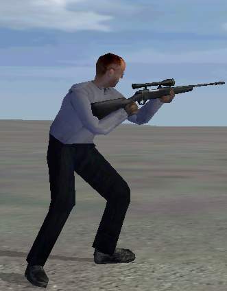
The gun we are going to make is nick-named “Stalker” and its a sniper rifle from Browning. Here, have a look:
Cool, isn't it? Well, it ain't going to appeal to everyone, but its the gun we`re going to make. Why this one, you say? Well, first of all we got a great side-shot of the gun on their page, its mostly black (makes texturing screw ups easier to hide:) ) and most of all, it looks pretty cool!
So, here is what you need to do to get started:
- Go to where Bulldozer is installed and make a folder named “stalker”.
- Download the texture files Brsseb_lesson3_start.rar from bottom of this page and extract them to the folder.
When you`re ready to start, go to next page.
Placing vertices
First we must create the actual gun model. Do this:
- Fire up o2 and Bulldozer and save the new file as stalker.p3d in the stalker folder you made earlier.
- Activate front view, press “A”, click RMB (right mouse button) and select “load Texture”. Find your Stalker folder and load the “blueprint.paa” file.
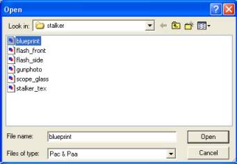 Load the texture we are going to use as reference
- The draw a box about, say 80% of the grid background. Then hit RMB and select “Correct Aspect” to ensure that the image dimensions are of the right scale. Also select “Horizontal Mirror” from the same menu so that the gun is pointing left.
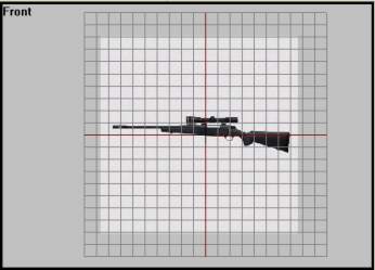
- Hit F4 to leave texture mode. The front view should look like this:
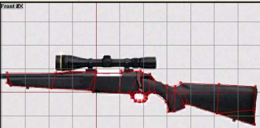
Now me must model the side shape of the gun. We do that by outlining the gun profile with vertices. That means we use “insert” at various points around the model. Later we will create faces on these vertices. Lets start with the back, shall we:
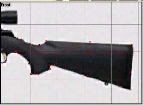
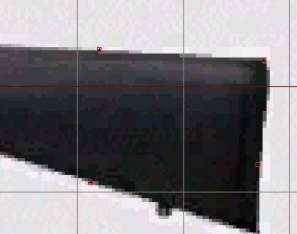
Zoom in on the rear gun part and start placing vertices using your cursor and the “insert” key. Start somewhere and work your way around the shape. Exactly where to place each vertex is not something you can learn just like that, it comes with modeling experience. Trial and error, that is. Here is how it could look like:
Note that there are few vertices at the strait points and more vertices where there are more round and soft shapes. Remember that we are dealing with polygons and therefore there are only straight lines between points. So we need to have many vertices where the model is supposed to have a round shape.
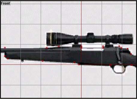
Now lets have a look at the middle section (leave out the trigger area and the scope right now). Here is my suggestion:
Doesnt look too back, does it? The main shape is there, at least, Note that we are not going any more left right now, the front section (muzzle etc) will be made of a small cylinder structure later. The same goes for the scope; later.
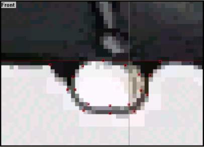
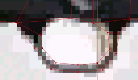
Now for the hard trigger area. This is the roundest shape on side view and therefore need many vertices to look good. Remember that the area between vertices will be filled with faces, so we need an inner and an outer vertice ring, like this:
OK, so it ain't pervert. Its sometimes hard to imagine how the vertices will look once we have made faces, but don't worry. its easy to move them later. And we haven't made the actual trigger yet, we`ll do that later.
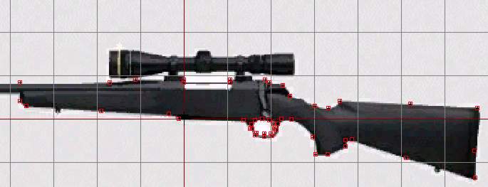 What it should look like so far
When you`re happy with your vertices (If you ain't, move them, add some or delete some to get the right shape), move on to the next step. And don't worry of some are a bit outside the background texture, “blueprint.paa” is only for reference, we use another one for the actual texturing.
Making faces
Now its about time to make the vertices do their job. Lets start with the rear gun section. Making faces is easy, you select 3 or 4 vertices and hit F6 to make a face. If you have read some basic o2 tutorials, you`ll know that every face has a “face normal” or a “direction”. That means that a face is normally only viewable from one side, the direction of the face normals (little blue lines poking out from each vertex). I assume you already know a little about this (if not, find a o2 interface tutorial or any 3d tutorial that deals with polygon modeling).
You should also heard that o2 supports faces created with 4 vertices and not just 3 as in big-shot programs like 3dsmax. That way we can use less faces than normally and still use 3-vertex faces when needed. We will select 4 or 3 vertices and create faces on them using F6. Be careful to not overlap faces, that can make your model flicky and look bad ingame.
I`ll show you how to make your first face:
- Zoom in on the rear gun section. We`ll start with a 4-vertex face.
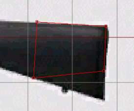
- Select the 4 vertices as indicated on picture below:
- Hit F6 and a face should be created.
Now we must make sure that the face is “facing” the right way. When I did this, my face direction was going from me in front view, not towards me as I wanted. So I had to reverse the face direction to make it the right way. Remember the trick I talked about in lesson 1, to see if the face is facing you? Go With the face selected, go to menu “View→Fill solid faces”. Now, if the face is filled red, you know that it is facing towards you, but it if seem do disappear (it will go black and be hard to spot due to our black texture), it is facing the wrong way. To reverse the face direction, hit “W” key. Remember to make all faces face the same way during the rest of the page.
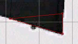
Now we have our first face. Note that we need to use a 3-vertex face just below our first one, since there are only 3 vertexes in that area. Select them using F4 (vertex select mode) and hit f6 again. Now o2 is pretty smart and it should face in the same direction as the last one, but check it out with the “Fill Solid faces trick” anyway.
Now , work your way around the rear part and create faces between the vertices. Use 4-vertex faces where you can and 3-vertex-faces where you have to. Make sure all is facing the right way and that none overlaps each other. You can delete a face without deleting the vertices. Just select the face (F4 and all vertices in the face) and delete it by hitting “D”-key.
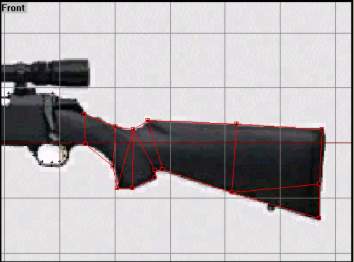
Here is how it could look like when done:
Another great way to ensure all faces are in the desired direction is using the 3d view with “Face Culling” turned on (View→Face Culling or “F” key). When face culling is on only the faces that are pointing in the camera direction are drawn.
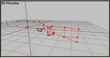 3d view with selected faces with face culling on. Since all faces are shown, they are facing the right way
Let me show you why this feature is so great for searching out wrong-pointing faced. I will now select one of the faces and reverse it. Se what happened in the 3d view:
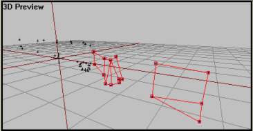 3d view with selected faces with face culling on. There is now a hole it our structure, which means one of the faces are the wrong way
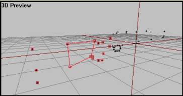 3d view with selected faces with face culling on. If we now move the camera and have a look at the back, we find our AWOL face again. As you can see, this is a much better and faster way to find bad faces compared to the “Fill Solid face”-trick I told you about earlier
Now if you have understood the above, applying faces to the rest of the model should be easy. Just be careful, take it slow to make sure all faces are the right way and that none overlaps each other. Here is some pics of how it should look like:
Lets move on, shall we
Applying depth
So, our basic model is shaped up. Hey, it even looks like a gun, right now. But that only in front view (and finally, if you've been wondering why we have been using front view for our side shape, its because that's the way it is done with weapons. Dunno why. If we don't do this, the gun will be pointing in the wrong direction when someone tries to use it ingame). Right now its just completely flat. Lets do something about it:
- Select the whole structure using CTRL-A (or F2 on any vertex).
- Activate left view without loosing the selection (Alt + LMB).
- Now hit CTRL-C to copy the structure. Then hit CTRL-V to paste the new copy. It will be at the same spot as the original.
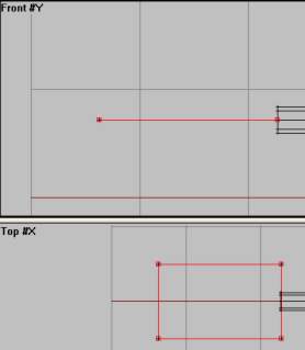
- Lock the x-axis and move the copy a bit to the right using RMB.
- Note that the copy`s faces are the same way as the original, to the left that it. But we now want them to point the other way, so with the copy selected hit W to reverse its faces.
- Now it should look like this:
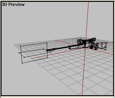
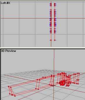 Front and 3d view with both structures selected. Note that here is face culling turned OFF just to show up everything in a single picture
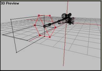
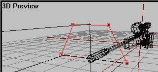
Now we must patch the two sides together. That means selecting 4 and 4 vertices and making faces. The easiest way to do so if using the 3d view. The hardest part in this is placing the camera right and selecting the right vertices. I`ll help you with the first one:
- Position the camera as in the picture below and select the highlighted vertices.
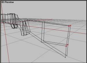 3d view with face culling turned off
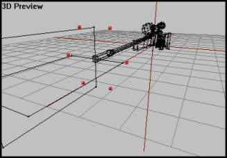
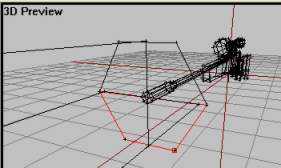
- Hit F6 to create the face. Then make sure that the blue lines are pointing out of the structure like in pic below. Use W tor reverse the face normals if not.
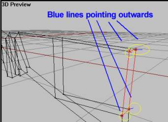 3d view with face culling turned off
Do the same thing for the whole model! Yes, its hard and boring work, but its really good modeling practice. Make sure to select the right vertices, its so easy to select the wrong ones if you are in a bad camera position. Use the other views combined with the 3d view as a guide. Afterward use Bulldozer and the face culling trick in 3d view to look for leaks (faces pointing inwards of missing).
In the end, it should look like this:
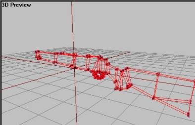 3d view with face culling turned off
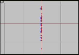
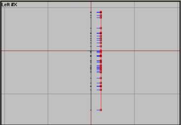
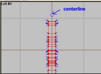
And, yes, one more thing. After you`re done, select the whole thing using CTRL-A. Then, in left view, lock the x-axis and move the whole shape to the left. Try to place it so that the middle red line on the grid is in the center, like in picture below.
Phew, that was a lot of work, don't you think? Well, I'm glad to tell you that the hardest bits are over. If you made it so far, you should be fine in the next ones too.
Muzzle and scope
Our gun is now really 3d, but its missing something, mainly the front section. We will make this one now out of a standard cylinder. Lets go:
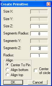
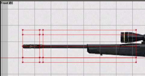
- Activate left view and hit F8 to create a cylinder shape. Use 8 in the “Segments Radius” and 3 in “Segments Z” .Hit ok.
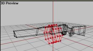
Now in 3d view you`ll see the cylinder. Its pointing in the right direction but needs some scaling down.
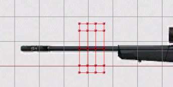
Head for front view, and use RMB to move the cylinder to this position:
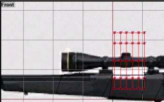
Lock the x-axis using x-key. Select each column of vertices using F4, and move them so that the result looks like pic below.
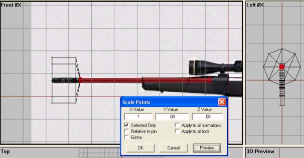
- Now, select the two rightmost columns of vertices, be careful not so select vertices from the main gun structure. Choose Points→Transform3d→Scale from the menu. Leave the x-axis as 1 and try to find a decent value for the y and Z box (whatever the value, z & y must be the same value, or the cylinder will look squeezed). I cant give you an exact value, since your model might not be of the same scale as mine. But for me something around 0.1 for y and z worked fine.
- Do the same thing with the last two columns of vertices, but keep their y & z scale values a bit higher, since the muzzle is bigger in the front. For me, z and y values of .12 worked fine.
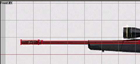
In the end, it should look like this:
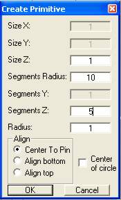
Now we must create the scope and we use the same process as above. We create a cylinder with several divisions and resize each and everyone of them. We also need two boxes for the scope supports beneath it.
- Activate left view, hit F8 and type enter the values below:
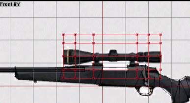
- Go to front view and move the cylinder structure like this:
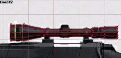
- Then, like we did with the muzzle, lock the x-axis, select and move each column so it eventually looks like below.
- Still same thing as before, use 3d scale to get the right look and feel of the scope. Your values are not the same as mine, so experiment a little with the y and z value. Don't touch the x-value though.
The scope should end up like this:
Then we need the two blocks right below the scope to hold it in place. This should be easy for you to make now and you could make them by outlining the shape with vertices, making faces, adding depth and fill in the gaps with new faces again. Just like we did with the main weapon profile in the start. Here are the ones I made:
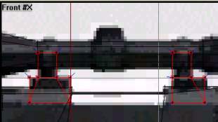
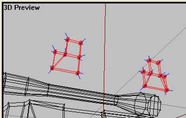 The two structures for the scope. (Note: Moved them away from the weapon just to show them better on picture)
Anything more then? Yes, the trigger itself. It doesn't show up on our picture, so we`ll just do some free-hand modeling. After all, this is just a tutorial and the model we are making are of pretty low-polygon quality. Here is how the one I made look like:
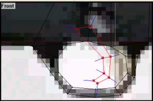
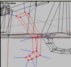 The trigger structure. (Note: Moved away from the weapon just to show it better on picture)
You`ve done it. The model is finished!
Now lets do some texturing, shall we?
Texturing
Now we must put some cool textures over our basic gray color. All textures are in the zip file you downloaded at the start and should now rest in your stalker-folder. Lets go:
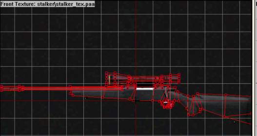
- In front view,select all (CTRL-A) so that everything is red. Hit A, RMB and choose load texture. Load the one called “stalker_tex.paa”. Also, RMB and choose “Horizontal Flip” to make it face the right way.
- Now, comes the hard part of scaling the texture so that it fits our model pretty accurate. Use CTRL-SHIFT-Up/Down/Left/Right keys to scale it. Remember to RMB and choose “Correct Aspect” from time to time so that the texture doesn't get deformed. I know its hard, and it would have been easier if we had cut the texture in pieces, but try anyway. And remember this is a tutorial so there is no need to get it absolute right. I eventually was satisfied with this:
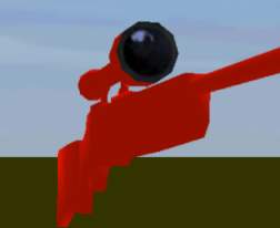
When you`re happy, with everything selected hit “B”-key and the texture should be applied to your gun model. Check it out in Bulldozer. Not bad, eh?:
So, its not going to win a beauty contest, but it doesn't look too bad for a tutorial model. At least not that bad, anyway. I think it looks pretty cool. One thing though, it could need a better front and rear for the scope, some glass-looking texture. There is one in your stalker-folder so lets apply it now:
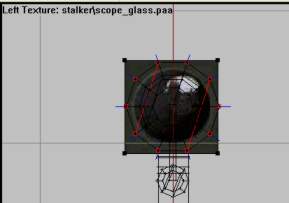
- In front view, RMB click and choose “unload texture” to remove the texture. We`re done with that one. Now, zoom in on the scope front, hit F4 and select the scope front column like this:
- Activate left view without loosing selection (Alt+RMB), hit A key, RMB and load the texture named “scope_glass.paa”
- Draw the texture box around the scope face. Use Correct Aspect to ensure right image dimensions.
- When you`re happy with your texture placement, hit B to apply it to the scope. Check it out in Bulldozer and try again if you messed it up. This is my result:
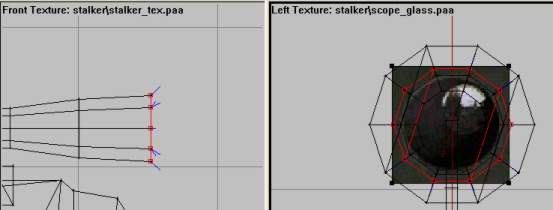
Now do the same thing to the other end of the scope. Just follow the same steps as above. Select the rear scope vertice column using F4 in the front view, go to left view and scale the glass texture so it fits the smaller scope end nicely. Then applying it with B and check out in Bulldozer.
Here is my result.
And that way texturing, my friend. Now the hard modeling is over, just some simple LOD stuff and the making of a basic config-file for weapons left. Go go go!
Memory LOD
As in all ofp addons, we need to sort things out in LODs. But for guns we only need one, the MemoryLOD. And it contains only 4 vertices! Simple stuff, really. Lets begin:
- Create a new LOD and change it to “Memory LOD” by RMB and choosing “properties”.
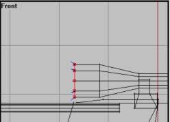
- Go to front view and zoom in on the barrel like picture.
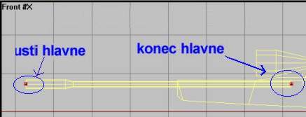
- Place a vertex on the center of each end of the barrel. They must be on the same height (or the gun will not shoot strait), so make only one, lock x-axis and drag-copy the next one using RMB+Shift and move. The result should look like this:
- Then, remember in many of the LODs in Lesson 2 we selected and named single vertices and called them names using Czech words?. Well, do that now and call the vertices the names on the picture above. “Konec hlavne” means end of barrel and “usti hlavne” means start of barrel. If you don't know how to save selections, see lesson 2.
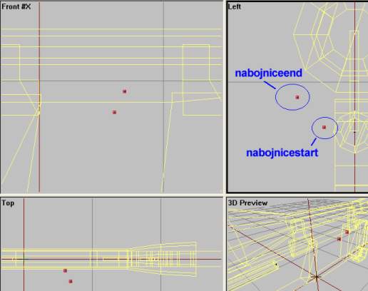
Now the gun can fire right. But we also need to indicate where the gun should spit out the empty cartridges. Just like the barrel, we need a start and stop position since the cartridges are “shot” out of the gun. Their placement isn't all that important, so I just give you a 4-view picture of how I positioned them. Save each of them as selections named as in picture. “Nabojnice” means cartridge-case in english.
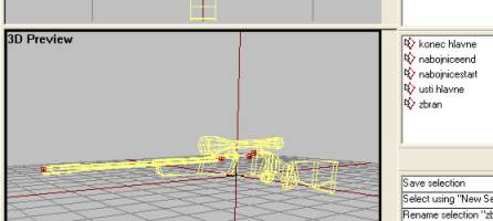
Finally, we need the 5th and last named selection called “zbran”, which simply means weapon. The selection consist of all four vertices, so just hit CTRL-A in Memory LOD and name the selection “zbran”.
Here is the selections you should have made in this part:
That's all the LODs we need for a weapon addon. No kidding. Move on.
The muzzle flash
Well, OK so we weren't all done with the modeling stuff. I guess I lied a bit there. But this is very simple.
If you don't already know, the flash that occurs when firing most guns in OFP is no fancy special lighting effect or anything. Nope, its just a simple model with transparent smoke-textures on it that occur the split-second the weapon is fired. Disappointed? Don't be, because its easy to make and looks good enough anyway.
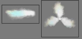 Have a look in your stalker-folder and check out the two textures flash_side.paa and flash_front.paa.
Lets get this over with quickly, then:
- Go back to the “0.000” LOD.
- Activate the top view and then find “create-plane” on the menu. Hit ok. Just after you hit OK on the dialog, hit F6. The blue lines (indicating face direction) should go away and the plane is now a double sided face. It is now viewable from both sides, check it out in Bulldozer and 3d view with Face culling on and then off. Cool, eh?
- Now move the plane along the x-axis in top view (using lock x-axis), make it a bit more like a rectangle. Then, in front view, lock the y-axis and move it upwards. It should look like this in front and top views:
- Now we apply the flash_side.paa to the plane. Since this is a double sided plane, the texture will be viewable from both sides. Activate top view, zoom in on the plane and hit “A” key. RMB click and choose Load texture. Load flash_side.paa and drag the texture around the plane. Make sure that BOTH sides on the plane are select, not just the one. Do that by making sure that both sides are grey in Bulldozer. If one is red like the rest of the gun, use F2 and select one of the plane vertices. Then apply the texture using “B” key.
- Check it out in Bulldozer. It should look like this:
- Now that we have one horizontal muzzleflash plane, we could need a vertical one. This time we simply copy the one we made and rotate it.
- Select the flash plane, CTRL-C to copy and CTRL-V to paste. Then on the menu find Transform3d→Rotate.. and rotate the new copy 90* on its X-axis (if you have the front-view active, that is). The result:
We need one other muzzle flash, a circle for the flash_front.paa so that the flash is visible when looking strait at the firing gun (aka getting shot at).
- Activate the side view and find create→circle on the menu. Make the “Segments Radius” from 10 to 6 and hit ok. Move and resize the circle so that it looks like this in 3d view:
- But we need double sided faces, so with the circle selected, press “D” do delete all faces on the circle so that only the vertices are left, like this:
- Now we must make two double sided faces by using F6 twice (!) on each face. In Select the 4 upper vertices and hit F6 twice.
- Then select the bottom 4 vertices and hit F6 twice to make the lower face.
- If you`ve done everything right, you should see a roundish-looking shape at the barrel end with both sides visible in Bulldozer.
Now we need to texture it. That's easy, ain't it? You`ve done it many times before. Just select the circle using F2, hit “A”, load the flash_front.paa, draw around circle in side view then apply it using B-key. Routine, isn't it?. Soon second-nature, I hope. Well, anyway, this is the final result:
Ok, almost done with our model now..hang in there. We need two simple named selections in our primary LOD, “0.000”. OFP needs to know what parts are the gun model and what parts are the muzzle flash. So select all the muzzle flash parts (3 structures, two planes and a circle), and name them “zasleh” (“flash”) in the named selection window. Then you need to select all the other parts; muzzle, main gun body, two scope holders and scope, trigger, hmm..anything else?..no. Name that selection “zbran” (weapon).
And if everything is done correctly, you are now finished with the model! Great job. Look trough the previous steps and make sure everything is right. And check that the texture paths are right (we learned how in lesson 1). Ok, done?. Configfile next, then.
The weapon config file
Only one obstacle away from testing our model in-game. Now that has to be good thing, doesn't it?. Well the bad thing is that our configfile is on the wrong side of “very confusing” for a any beginner. So, as Ive done before, I will lay out the configfile and explain only some key attributes and leave the class-inheritance stuff for you do learn from an other tutorial. In fact, you could just move on to the next step if you want, but I advice you to read this and at try to get an overview of what is going on in the configfile.
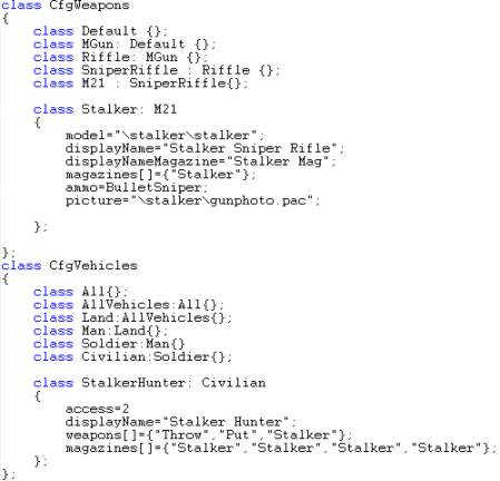 Snippet from the most important part of the config-file. There are more stuff in the configfile, but only the above is the interesting parts right now
If you have some Object Oriented programming experience, you`ll see that Ive inherited (aka “stolen”) most of the M21 sniper rifle and changed some key attributes. The ammo is regular sniper ammo and both the gun and ammo have the same name (so if you are to add the gun and ammo to a person in the editor you would write this AddWeapon “Stalker”; this AddMagazine “Stalker”;. The displayname is “Stalker Sniper Rifle” and Ive also prepared a small photo of the gun for the ingame journal on the map screen called “photo.pac”.
Then Ive also made a civilian equipped with the gun. He is called “Stalker Hunter” and carries the rifle with 4 magazines. There are 20 bullets in each magazine, just as the M21.
OK, enough config-file now. Lets just leave it alone and test our model ingame instead. Roll on.
Finishing up
OK, lets do this. Its time to test it ingame! Run PBOTool, select the stalker-folder and save it as stalker.pbo in the OFP addons folder. Then start up OFP. Go to the editor and find the civilian called “Stalker Hunter” on the Civilian→Man list. Then come back to the lesson after testing.
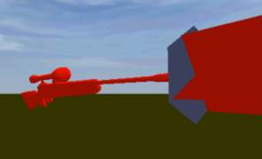
You`re back, huh? What? Something is wrong, you say? The gun is bigger than an airplane? Like this, for example:
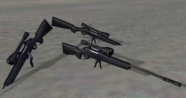 Now THIS would be fun in multiplayer. But its more like “Big Bertha” than “Stalker”…
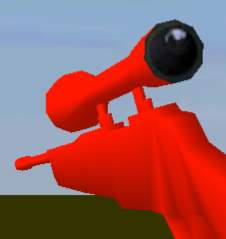
Well, thats right. Its not scaled right yet. Hey, at least it is pointing in the right direction! And it works, doesn't it? With sound, cartridge shootout, muzzle flash and proper scope? Not bad, eh?
You need to use the 3d scale tool in o2 to make it the right size (remember when scaling to tick on the check box “Apply to all LODs” so that the vertices in Memory LOD follows the rest of the model). Normally this is just trial and error. Scale it down a bit, compile and test it. It it still too big, do the same thing again. Im not sure how big the thing is in real life, maybe the web site can give you a clue. Just remember that each grid square is 1 meter.
One thing you can do to help you, is to “merge” a p3d file of an other sniperrifle, like the M21 or the Dragunov. That will make it easier to scale your own model. Also, it will give you a hint on how the model should be placed to rest nicely in the hands of a soldier. Note that you cant load up the M21 model from your OFP copy since the developers have binarized their files. But they didn't lock up the model files from the first single player demo of OFP. So if you want a p3d model of, say, the M21 sniper rifle, go to my links-page for clues on where p3d's from the demo can be downloaded.
You can also merge user made models, other sniper rifles downloaded from the net. Just use PBOTool to unpack them and have a look at their p3d file. When you`re done scaling and moving the gun into position, remember to move both the gun in “0.000” LOD AND the 4 vertices in Memory LOD). That's trial and error too, I'm afraid (if you haven't downloaded any demo or unofficial addon p3ds, that is).
Here is how my model looked like in the end. Pretty cool, I think.
One thing, though. You have noticed that we only have one model LOD, “0.000” in our model. Normally we have at least 3 different models, one more detailed than the other. This is to compensate for the different hardware settings and the distances the model is viewed from. No point in having the machine draw small details, like the heavy-polygon trigger area when the gun is view from a distance far away. This is very important to know if you are to release any addons. Look at other addons and see how its done, because since this is just a simple tutorial I'm not going to cover this here. Its not that hard and you should be able to figure this out for yourself.
But now its time for you to feel proud because you just made your first weapon in OFP! As usual, you can download the final model Brsseb_lesson3_done.rar below. And I welcome any feedback on my lesson on hotmail.com (or via MSN directly, I`m online almost every day).
That concludes lesson 3. Happy sniping.
Download samples and ready files; OFP.Brsseb_Lesson/ Torrent Magnet from below:
magnet:?xt=urn:btih:40aac3407210ddb8ffcee06cdb009c0b099ccdce&xt=urn:btmh:122046986f756bcebf9744dc9f81bc3fc736a54e164113ec62e18c827a4a06271364&dn=OFP.Brsseb_Lesson&tr=udp%3a%2f%2ftracker.opentrackr.org%3a1337%2fannounce&tr=udp%3a%2f%2ftracker.openbittorrent.com%3a6969%2fannounce
Notes
This tutorial was written by Brsseb in ofp.gamepark.cz/_hosted/brsseb/, it was posted here with his permissions, thank you Brsseb!


