Table of Contents
Lesson 8: Creating your first Building
Creating your first Building by Brsseb
Preparing for the lesson
Welcome to the 8th tutorial were we will make our very first building, a cute little house that we can walk into, open/close doors and maybe climb a little ladder too! First things first:
- OFP (daahhh), O2 and Bulldozer
- Basic understanding of the O2 interface
- Having fully understood stuff from lesson1 (like creating LODs, selections etc)
- Note that it says “lesson”, not tutorial. That means that the info in this lesson I assume that you have learned some stuff from the other lessons. You must have done at least 3-4 of the previous lessons to get something out of this.
- PBOTool and TexView or similar program
Im assuming you either have done all or most of my other tutorials or are experienced in modeling and the o2 interface, because I'm not gonna hold your hand anymore when it comes to texturing, placing vertices where i say they should be. Making buildings is an easy job because it involves mostly basic shapes like cubes and not much more. Its just a manner of placing and scaling them right and adding a proper texture. Not much advanced selection naming for the LODs either since buildings don't move or have much special features.
Roll on:
The tutorial model
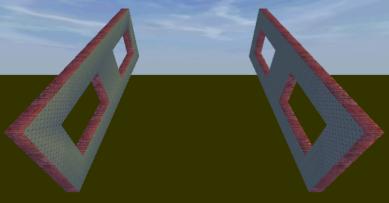
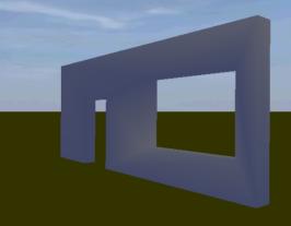
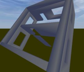
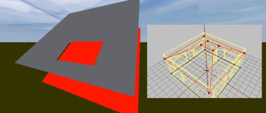
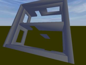
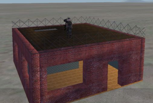
In this tutorial we will make a small house like on the picture below. I'm not gonna give you a done model right now since this is mostly a modeling tutorial, but i will supply you with textures and a configfile. We will create the structure part by part (a part may be a wall, floor, ladder, etc) and finally put it together as a working building, getting it ingame.
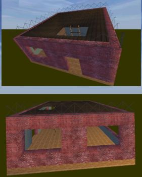 Two shots of the building we will be making
We will have two floors;a first floor with two doorways and windows, and a ladder up to the roof.
Get the project folder with textures and configfile Brsseb_lesson8_start.rar from bottom of this page.
That's it. Start o2 and bulldozer, and save the new file as “firsthouse.p3d” in the firsthouse folder included in the zip and lets roll! (Hint, as you progress, make backups of the p3d file in case you mess something up, and you probably will (I did it 2-3 times)!).
The main floor and editing vertex coordinates
We`ll start with the main floor. Its basically just a low profile box, very easy to make. We will do each part and texture it before we move on to the next, and then assemble the whole thing at the last moment (since buildings can get very hard to edit once all walls, roof and windows are in place).
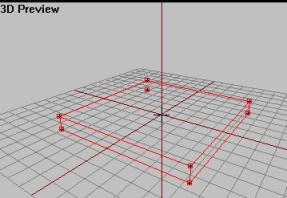
- In top view, hit f7 and enter 10 in both sizeX and sizeY field and hit OK. This is the basic floor shape, but its a bit thick.
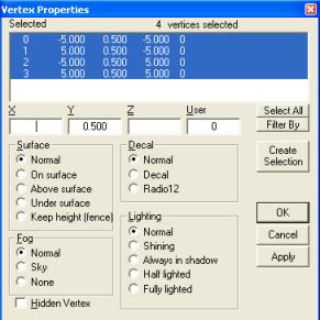
- In side view, hit F4 and select the top 4 vertices. Then hit shift+E. This will allow us to edit the vertices coordinates in 3d space. Now this is the hard part of this kind of modeling. Since o2 dont have proper “snap-to-grid” functions like other 3d program, you must manually edit the coordinates to get the vertices where you want them. We want the floor about 0.10 meter above ground level (to make sure floor don't get buried or flicker with the island ground texture), and say .4 into the ground (to compensate when the building rests in uneven terrain).
- So here is the think, hope you have basic math skills covering Coordinate systems. With all four vertices selected, the X and Z field on the window is blank, meaning that all or one of the selected vertices have different X and Y coordinates. But the Y field is showing meaning all four vertices share this value, as you see in left view that all of them lie on the same plane (or level). A box is 1 m in height on default when we created it, so its 0.5 above and 0.5 below ground as all objects are created on the center of the p3d file. So lets change the Y-field to 0.1 and hit ok.
- Then still in left view select the lower 4 vertices, shift+E and set its Y value from -0.5 to -.4. (not much of a big deal, but at least ypu learn how it all works).
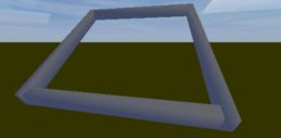
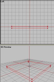 Here is the final floor structure, a 10mx10mx0.5m box
Make sure you got that trick of changing the coordinates of vertices using the shift+E box, because its vital for the next steps. Play with it, try changing a box or a cylinders shape without using any scaling functions. Changing the shape of a structure using this method is a much more accurate one than relying on free scaling using the mouse and the CTRL button. And if we are to make our house of parts, me must make sure that all parts are aligned so that the pieces fit when we assemble it.
Now select the whole floor structure and name a selection for it named “floor1”. this don't have anything to do with the OFP engine, its just so that its easier to select our floor structure later during assembly.
Lets texture it so that the floor is truly done. We`ll use the file named “wood2.paa” for this. I assume you can load textures and know how it works (lesson 1), but ill help you a little on the way since you will be doing this mostly on your own later in the tutorial.
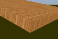
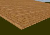
- In top view, load the wood texture and drag a 1mx1m box somewhere in the left view. Yes, its its not like on the tut 1 crate, this is called “tiling a texture”. We don't drag the texture over the whole floor like on the crate, because the texture will look awful when stretched across a 10×10 meter structure that the floor is. After making sure that the texture is of right scale, hit Apply. Check out the result in Bulldozer.
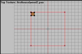
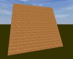 The tile able texture gets copied, side by side, all over the floor. Great if a texture is small and the surface to be textured is quite large. This way the texture look better ingame.
The floor structure is nearly done. It still have some ugly sides since we only applied texture to the whole structure from the top view, leaving only top and bottom face nicely textures. All the other sides are looking you fix that easily, its like you did in lesson 1. Select all 4 sides, one at a time, and apply the same texture to it (don't worry it you don't get the textures lined up right since this it just a practice tutorial). You should be able to do this yourself.
If the floor is ready textured, leave it in “0.000” LOD. Then make a new LOD and enter it. We will have one LOD for each part, and at the very end merge them together. Leaving the floor in 0.00 LOD will give us a nice yellow ghost picture of the floor for reference when creating the walls, which are up next.
The walls
Lets start with the walls. We will have two wall types, one for the right and left side with two windows in them, and a front and rear wall which have one window and a door in each. As you might guess, we will make one wall type and copy it to make the other. Lets start with the left and right ones:
- In left view, create a plane (Plane, not a box this time) with SizeX=10 and SizeY=4.
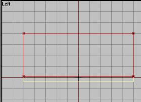
- Select the lower two vertices, shift-E and change the -2 in Y-field to 0.1 (where our floor ends). Select the top two vertices and change their height from 2 to 4.
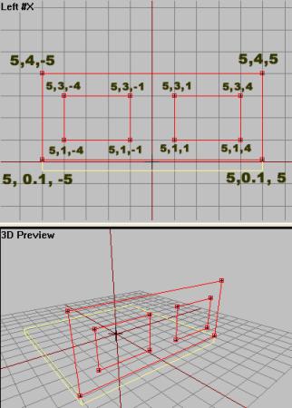
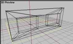
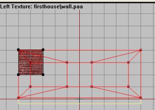
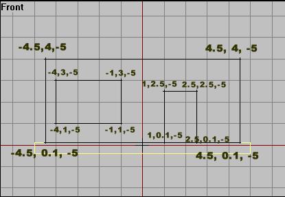
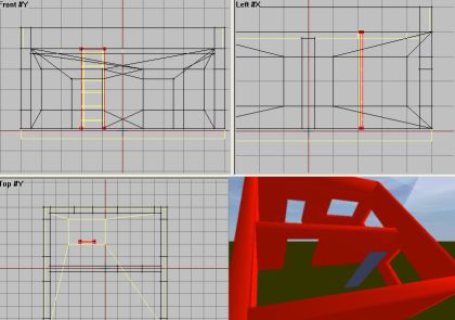
- Now we must move the plane away from the center and out to one of the edges. Select the whole plane and shift+E. Change the X-field (that is shared for all 4 vertices) to 5. Before we create the thickness of the wall, we must make holes for the two windows. In left view, select the whole plane. Then either copy and scale the points twice, or make 2 new smaller planes inside the wall shape, making sure all share the value if 5, like on the picture below. To make the wall a bit tidier and more structural, its advised that the two window holes are the same height and size. Here is a picture of the wall. Make the two window planes of dimension 3×2 meters. Change the window planes` vertices so that they are aligned and right. Here is a pic of the final wall outline with x,y and z coordinates on each vertex. Remember all vertices share the X-position, which is still 5.
Still with me? If you`re not, play around with the vertex placement some more untill you get it right. Next step is this:
- Select all 3 planes and press “D” to delete all the faces.
- Then fill in the wall with new faces making sure that you don't cover the window holes and that all faces are facing the right way, like this:
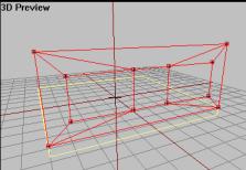
- Now lets add some depth; in top view, select the whole structure, lock the x-axis and drag-copy the structure to a new location just 0.5 meter behind the first one, reversing the faces (W). This will be the inside of the wall. Use the shift-E trick to align the vertices to the new X-coordinate to 4.5 (its 5 for the outer part). Then fill in the gap between the two structures with new faces to make it a solid wall, like this. Remember to create the faces for the inside window frames and keeping the faces facing the right way (All this was learned in lesson 3).
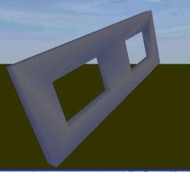
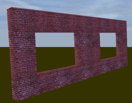
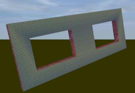
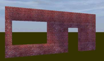
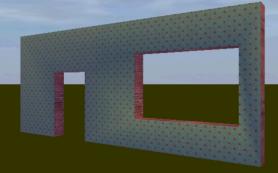
Ok, the wall structure is in place. Lets texture it and duplicate it to make its alter ego, the wall on the oposite. Texturing is the same thing as last step. But we need one texture for the exterior and another one for the inside. The outside texture is called “wall.paa” and the inside is “wallpaper.paa”. Both textures are tile able, so you must use the trick from last step to avoid the texture being stretched, especially the small wallpaper texture. I'm not gonna help you on this one, your on your own. Here are some images of how i did it. Try to get it in a similar fashion, if not better ;). One hint is to drag the “wall.paa” texture as a 2x2m box and use that in all view ports so that you don't get too much different texture scaling when going around the wall adding textures. For the wallpaper texture, about 1/4 or less of a 1x1m grid seems OK.
Thats done then. Now select the whole structure, copy and rotate it so that it fits nicely on the other side. You should be familiar with rotating and such things by now, right? Using shift-E trick on selected vertices make sure that its properly aligned with everything. all should be the same, just that the values for the X coordinates for outer and inner is now -5 and -4 instead of + 5 and +4.
Finally select both walls and name them “Left&Right_walls”. Create a new LOD and move to the next step, the front and rear walls.
Front and rear walls
Time for the front and rear walls, which will have one window and a door each. First we only do the basic wall with holes in it. As creating these walls are similar to the previous ones, except for size and this has a doorways instead of a second window, I will make this section shorter.
- In your new lod, create a plane in front view, making it 9 in sizeX and 4 in sizeY. Align the lower two vertices with the floor (0.1 m remember?) and the top two should have a Y value of 4. Give all 4 vertices a Z value of -5.
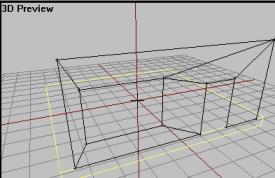
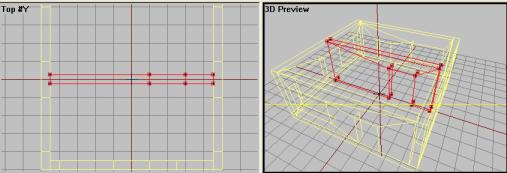
- In similar fashion as the last one, add two more smaller planes and align them as in this picture:
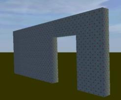
- Now select all, delete the faces (“D”) and make it so it looks like a wall, just like before. Be dead certain that all faces are the right way.
- As we have a wall thickness of 0.5 from the last walls, we will have this here too. So select the structure, drag copy it, reverse the faces and make all vertices aligned using -4.5 as the Z value.
- Fill in the holes with faces so you have a solid structure. Note that there are should be no face at the bottom of the door frame!
Now that we have a wall structure, we must texture it. We use the same textures as before, with the same tile dimensions (2×2. for the “wall” and 1/4 or less for the wallpaper texture). The result is something like this:
Now make a copy of it, rotate it in place on the other side, making sure all vertices are on the right place. Then select both of them and name then “front&rear_walls”. Make a new LOD and move on to the next part.
The inside wall
We will make one inside wall with an open doorway so that the house at least have two rooms and not just one big one. Its a very simple wall structure that uses only the wallpaper texture and has only a doorway, no window holes.
But just having the floor as a reference is getting a bit tired now, so we need to copy the 4 wall structure we just made into the 0.000 LOD so that we can get a better reference. Do this now, Simply go to both the wall lods, select all and copy it into the original 0.000 LOD together with the floor. This is also a good point to save a backup of your file in case you mess something up later.
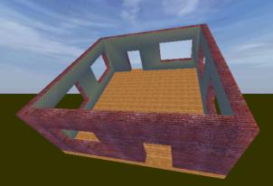 Our work so far (“0.000” LOD) with surely the worst wallpaper design of the century ;)
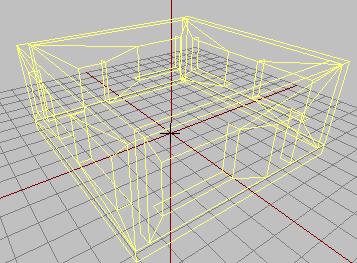 The new yellow reference image. Having the walls as a reference is important for the next steps.
Now lets make the inner wall. Its simple:
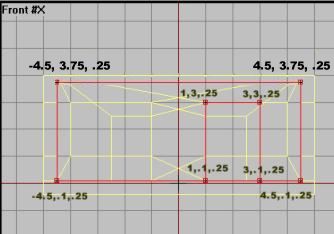
- In front view, create a plane. Select the left column of vertices and set their X-value to -4.5. Similar, set its right row to 4.5 so that the wall fits inside the house nicely. The top row of vertices goes with a Y=3.75 (because of the roof, more on that later) and the lower row 0.1.
- Now make another plane and form it as the doorway, just like you did on the last walls, lower row of vertices Y=0.1 and the top row Y=3. Also, move both planes so that their Z-coordinate is .25 (we`ll give the wall a thickness of 0.5 meter, aka from .25 to -0.25). See picture:
- Yes, then delete the plane faces, and make new ones to form a single plane structure with a door hole. Then copy and reverse the plane, and add the missing faces on the sides, making sure all coordinates are right. The wall should be exactly .5 m thick now.
As usually, texture the wall, this time using only the wallpaper texture.
When ready, name the wall “inner_wall”, make a new LOD and head for the next part!
The roof and the ladder
Now its time for the roof. We`re not gonna make a full 2nd floor, but its not hard. Its basically just copying the thing we have made so far and place it on top of this one, but we`ll stick to a simple open floor, watchtower-style, just to keep things simple. To gain entry to the roof, we`ll make a ladder too!
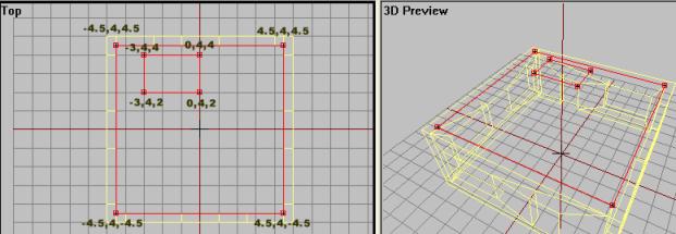
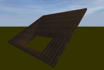
- In an new LOD, in top view, make a plane structure with settings SizeX=9 and SizeY=9. In left view using shift+E, change the pixel row Y-value to 4.
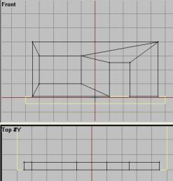
- In top view again, make a new plane, this time smaller and in the position indicated by the next picture. Also change its height to 4. This plane will be the hole in which the ladder will go.
- Now as we did with the walls, make a proper 3d structure of this with a thickness of, say, 0.25m. I assume you know how to do this by now.
- Name this structure “roof” and apply the “roof” texture to the structure.
Ok, now for the fence. We cant have our soldiers falling off the roof to easy, can we?
- In the same LOD, make 4 box structures, two of length 10m and two of length 9.8, leaving the wall thickness for all of them to 0.20 meters and a height in left view of 1 meter. Select all 4 fence structures and name them “fence”.
- Texture the fence using the “fence” texture. Make sure the texture lines up nicely and you get a good fence-look on it.
Nice! Now the ladder and the roof is done.
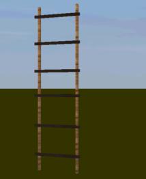
- Make a new LOD and in left view make two 4m high poles as in picture (don't have to be that accurate). Texture both poles using a woodish texture. I chose the “wood2” texture.
- Now make a single horizontal block and form it as a step on the ladder. Texture it using one of the woodish textures in the folder. I chose the “roof” texture.
- When one step is made and textured, copy it and place them out forcing the missing steps on the ladder.
- Name the final ladder structure “ladder”.
Lets position the ladder right:
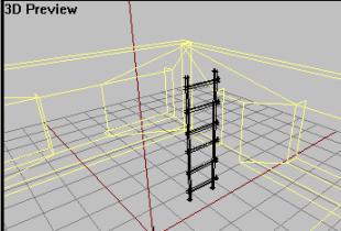
- Select the ladder structure and move (you might have to rotate too) it into position
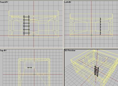 Move the ladder into position like in the picture above
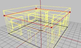
OK, that's the basic structure of the building. Now we gotta combine all the parts into the first “0.00” lod, because its time to make the other lods (Geometry, Roadway, etc. More on that in a moment). So, first make a backup of the file we got now (if you mess up a part or looses track, you can access the backup and pick the parts you need with no problem).
- Make a backup of the current file
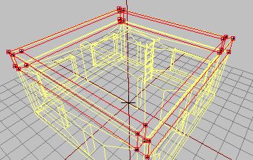
- Now start copying all the parts you have made onto the 0.00 LOD (not the basic walls, you copied them for reference earlier in the tutorial, remember?), and the end result should look something like this:
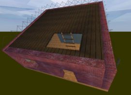 ll the parts gathered in the “0.00” LOD
- After all parts are copied to the 0.00 LOD, delete all the other LODs
Ok, lets do some proper LODs now, Geometry first. Move on.
Geometry LOD
The most common fault to do when doing buildings, is making the whole wall structures as a single object. Thats asking for trouble and most likely it wont work properly ingame. All the different walls should be separate pieces not connected to each other.
This isn't that important on normal view LODs like 0.000, so we could have combined all the walls. But for this tutorial i wanted to make the house fast to build, so i made all walls in separate pieces so we can use some of the original wall structures directly as Geometry walls.
- Make a new LOD and change it to Geometry.
- To back to 0.00 lod and select (using the labels) the following structures:
- “left&right walls”
- “front&rear walls”
- “inner_wall”
- Copy them and paste them into the Geometry LOD.
This leave us with just the basic walls and the roof. For some reasons that has to do with the Roadway LOD we`ll add later, there is no need to use the bottom floor or the roof as geometry. Doing so might cause some clipping issues ingame.
One problem; you might have spotted that we are missing a proper geometry structure for the rooftop fence. Without it people might fall off easily. The problem is that when geo structures get thinner than .25 meters, people might fall right through it if they are running fast enough (you might have noticed this in ofp, especially on some fences or buildings with thin walls). So that's why we cant just use the thin roof wall structure we made in the 0.00 lod.
To solve it its best to make a structure thicker than the one its supposed to cover. It might be noticed ingame and confuse or irritate the player (all hate invisible walls in games), but i think it will be OK for out simple fence.
- Make 4 cubes and shape them in the same manner as the 4 walls we made, except the holes for the doors and only 1 meter high. Thickness of .25 m (same as the default walls) will be OK.
- Move them into position above the roof.
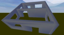
- It should look like this when you are done:
Only thing missing now is a small box structure to cover the ladder. We don't want people running right through our ladder, so we need this one. Its very simple:
- Create a box structure (F7) and form it so that it covers the ladder pretty much OK.
Now select all of the structures and apply mass to it. Lets make it, oh, something heavy…30 000 is a nice value. Then, with all components selected, go to Structure→Topology→Find Components to make o2 automatically add the needed “ComponentXX” labels. Deleting the old labels (inner wall, left & right walls) is not needed, but its nice to keep your lods nice and clean. Removing the textures can be done by selecting all of the components, then hitting “E” to get up the “face properties” window and delete the three “…” in the lower edit box. But again, not entirely needed since ofp ignores any textures for geometry lod structures.
Final geo lod like this (textures removed)
Then geo lod is OK. But we need some more LODs before we can test it ingame. Move on.
Roadway LOD
Ok, time for Roadway LOD. IF you have never heard of it before, its the lod defining walkable paths for ofp men and vehicles to walk around on. It enable you to enter buildings, drive up ramps with cars and a lot more stuff. All components in Roadway lod is normally made out of single planes (4 vertice faces either single or connected together with more planes).
The geo lod hinder objects to pass trough them,but as a side effect hinders ppl to walk on them too! So we need the Roadway to indicate where the player is allowed to walk around.
- First make a new LOD and change it to Roadway LOD.
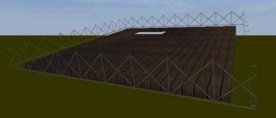
- Make sure the front view port is active. Hit Create→Plane and enter 10 both of the in the two upper edit boxes. This will place a plane the size of the building floor near the bottom.
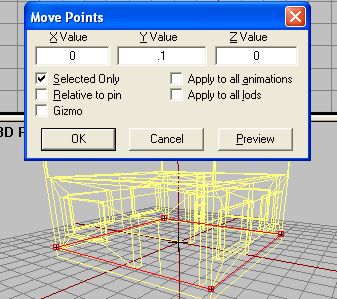
- Then, in Left view with the plane selected, go to Points→Transform 3d→move… Enter 0.1 for Y to mode the whole plane 10 cm upwards (our floor is elevated a bit remember? Hit Enter.
- Now we need the roof plane. Its basically the same sized plane, but with a hole for the ladder. Select, copy and paste the floor plane and move the copy strait up. You can use the menu Move-command once more, this time with an Y=3.9 (4-0.1=3.9 ;) ) This should move it just into the position of the top of the floor structure.
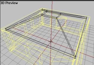
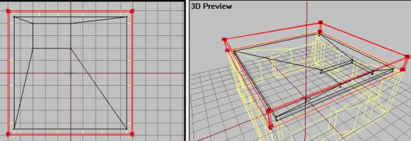
- Copy the top plane, paste and scale the new plane in top view so that it matches the hole for the ladder. You use the same vertex data as for the original roof hole, like this:
- Now, with BOTH top planes selected hit D to delete the face, leaving you with 8 loose vertices. Then make new faces (making sure all face upwards!) so you have a plane structure with a hole in it looking like this:
Notice that if we wanted to have a staircase or a ramp up to the roof instead of a ladder, you would just create a slope with a plane for the soldiers to walk on (make sure it is connected to both floor planes or you might get some trouble). Also, make sure its not too steep of you will have trouble climbing it. If this ramp is designed for cars and heavy tanks, then you should note that the steeper the ramp is the easier it is to get a puncturing or damage to the vehicle if you are driving a bit too fast.
You can do a lot of cool stuff with the Roadway LOD, but respect it because it can get you in trouble of you mess it up (units falling trough the floor, jumping and shaking around like crazy ,etc).
OK, that's Roadway LOD. On to the next one then!
View Geometry LOD
Once the Geo LOD is made, this one is usually easy, especially for buildings. Basically this is an LOD that helps the ofp engine how to render the house ingame relative to other objects nearby. Sounds strange? Sure is!
I can give you an example to show you what i mean. If you have made some addons you will know this problem:
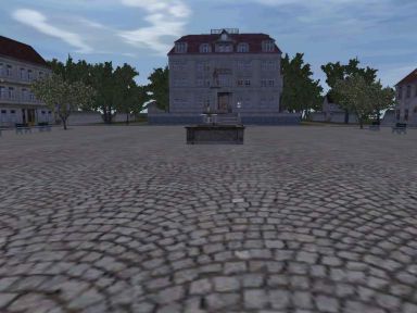 A nice screenshot from the Nogova capitol with the main office building down the street
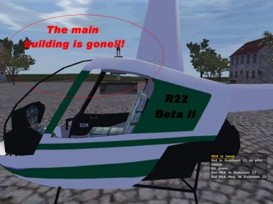 About the same shot just with an old version of my Robinson R22 in front of the building. Notice that even though just a part of the R22 is limiting my view to the house in the background, the result is that the ofp engine just skips rendering the whole house! Also trees and other objects are missing.
The problem is that the R22 is missing an so called “View Geometry” lod. This lod is similar to the normal Geometry, just that View Geometry deals with rendering (when I use the word rendering i mean the way ofp draws each frame) and the normal Geometry deals with mass and collision detection. Basically the View Geo tells the ofp engine how much the addon “cover” the scene and where the holes are (our windows).
Hope you understood some of this because its very important when making addons. Anyway, because our house is very simple, we can use a copy of our Geometry LOD as View Geometry directly, without any need for editing:
- Right-Click on the Geometry LOD lod in the LOD list and hit “duplicate”
- Change the new lod you get to “View Geometry”
The new lod is now identical to our Geo LOD, except the mass has been removed. View Geo lod also needs the component labels, but as we made them in Geo LOD we ca just leave them as they are.
Move on!
Memory LOD
Usually, buildings don't need Memory LODs. The exception is when the building have certain features, like a ladder.
Lets make the ladder working. Its very easy since we got only one ladder in our house:
- Make a new LOD and change it to “Memory LOD”
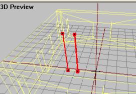
- Place two vertices in the following positions and name them “start” and “end” like on the picture.
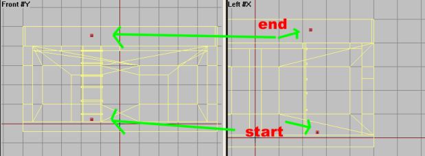 The ladder start and end points in Memory LOD
These vertices indicate positions for climbing the ladder. It can be hard to get the soldier to climb right and you might have to test ingame and then move the vertices around to get it to climb right. Thankfully i have done this for you for this tutorial and if you place the vertices like in the above picture it will look OK (for a tut model that is ;) ).
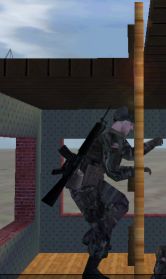
Notice that the way the vertices are used to indicate the ladder, there seems to be nothing in Memory LOD to indicate the direction of the climb animation! So how do we know what direction the climbing animation will run on? The truth is that even that it might seems strange, a vertex actually have a direction vector or heading! Finding out the direction can be tricky, so the easiest way is to make the two points and test ingame. If it climbs the wrong way (say you really want it 90* to the left instead) , you can easily just select the two start and end points and rotate them. But for the way our ladder is oriented now, the default vertex heading a vertex has when you create them will be just fine. But keep this info in the back of your head when creating your own ladders.
Ok, thats Memory LOD (for now). Move on!
AI Paths
You might have noticed that the AI isn't very good at navigating buildings or advanced objects, it gets stuck sometimes or just avoid it totally. To get AI to move around inside buildings properly, you gotta make some “rails” or “path” for the AI to follow. Without them, computer controlled soldiers wont enter your bulding properly.
Also, you might have noticed from the mission editor that some buildings have a number of “positions” that you can place soldiers in. We are gonna have some of that too.
- Make a new LOD and change it to “Paths”.
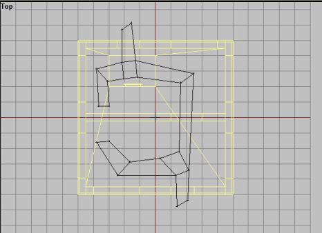
- In top view, place vertices and make make 4-vertice planes so that it looks similar to this figure (yes, it might seems strange..but do it anyway). Try to match my figure as good as possible and make sure no planes cross or come too close to the walls (the AI might bump in and get stuck!):
- Use 3d view to make sure that all faces are facing upwards
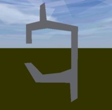 Top view of the path network in Bulldozer. Make sure all faces are the right way.
- Now we must name some key vertices on our path network. If you are pretty confused now, think of this network as a pavement or rail network for the AI to walk on. Its the path the AI will follow to ensure that the AI can navigate the building without bumping into stuff or get stuck. Now select a vertice one at a time and name them the labels on the picture below:
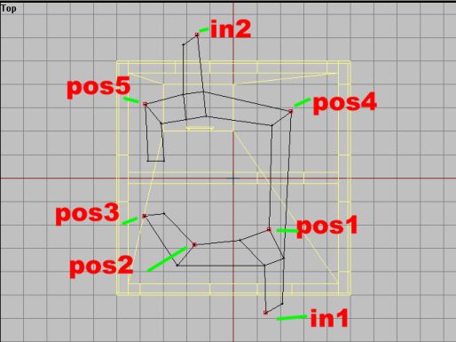 Name the vertices as in picture. Notice we have two entrances and five different positions that the AI can be stationed in. Also the AI should run trough the middle wall door and exit and enter the building pretty much OK.
- After that, select the whole path structure and go to front view. Hit shift+E and edit the Y-field to 0.2 to make the path structure hover a bit above the floor.
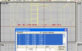 Make the path structure 0.2 m above ground level.
OK, pretty weird stuff but that's the way its done. The AI should be able to navigate our structure OK now. I'm not sure if there is a limit in the number of “pos” and “in” points, so you should be able to add more or less points easily for your own buildings.
If you got a building with a ramp or staircase connecting two floors, you got to make AI network for both floors if you want the AI to go upstairs. Its just about creating a second network for the upper floor in a similar fashion, then connecting them with a sloped face where the staircase or ramp is. This way the AI can use the stairs too. But we wont go into this in this simple tutorial.
Now lets get move on. Not much left now…
The configfile
As always I end a tutorial with a brief look at the configfile needed to get the addon working in ofp. Thankfully the config needed for a building is relatively short, so this shouldn't be much trouble if you followed my other tutorials:
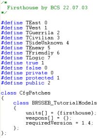 The first part of the configfile
Very simple stuff, just the standard define section (pretty much useless stuff for our house, but its becoming a habit to use it in all configs). Then its the all-important CfgPatches class where our house is defined. All in all, nothing new at all.
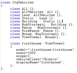 The second part of the configfile
Here it gets a bit more interesting, but not much ;). You can see that i classed our house under the ViewTower class. Al though our house may not be a strait viewtower, we need to use that class because a viewtower has a ladder. The usual “house” class don't have the ladder function, so we need to use the class “ViewTower2” (or any other class that support ladders).
Ah, enough code. Lets get the house ingame!
Last steps
Now we got all the LODs we need and the building is ready to go ingame. So, make sure you got all the steps right and that all files are in the “firsthouse” folder (the firsthouse.p3d, all the texture files and the config) and lets go! Fire up PBOTool and create firsthouse.pbo out of the folder, and put the resulting file in your addons-folder in ofp dir.
The house can be found under objects→firsthouse in the editor.
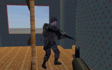 The AI can run though the house with no problems
Yes, we have done it! Our little house is complete, its got a working ladder, windows to shoot out and the AI can navigate it pretty much OK. Not bad, eh? Well, hope you have enjoyed the tutorial and learned the basics of ofp building creation. Still some stuff to learn, but this is the most important parts. Note that for the sake of this tutorials simplicity I skipped making a Fire Geometry LOD, since it was learned way back in Lesson 4. You will notice that without such a LOD you will be able to shoot strait trough the building. You can make a Fire Geo real fast by just duplicating the Geometry LOD and changing the copy to Fire Geo. See lesson 4 for more info on this type of LOD.
Brsseb_lesson8_done.rar is the final PBO, download below. If you had trouble with yours, check out my finished version. Extract it and compare the p3ds and see if you can spot any bugs if you had any trouble getting trough the tutorial. As always, drop me a mail if you need help.
As always, comments to the usual address (brsseb@hotmail.com) if you got trouble, spot some serious errors in my tutorial or got other stuff on your mind. Cheers!
Download OFP.Brsseb_Lesson/ Torrent Magnet from below:
magnet:?xt=urn:btih:40aac3407210ddb8ffcee06cdb009c0b099ccdce&xt=urn:btmh:122046986f756bcebf9744dc9f81bc3fc736a54e164113ec62e18c827a4a06271364&dn=OFP.Brsseb_Lesson&tr=udp%3a%2f%2ftracker.opentrackr.org%3a1337%2fannounce&tr=udp%3a%2f%2ftracker.openbittorrent.com%3a6969%2fannounce
Notes
This tutorial was written by Brsseb in ofp.gamepark.cz/_hosted/brsseb/, it was posted here with his permissions, thank you Brsseb!

